


2-14T-268-07
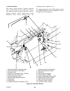
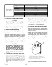
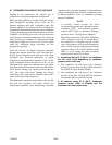
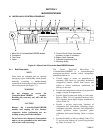
2.7 REFRIGERATION CIRCUIT WITH RECEIVER
Starting at the compressor, the suction gas is
compressed to a higher temperature and pressure.
When operating with the air-cooled condenser, the gas
flows through the discharge service valve into the
pressure regulator valve that is normally open. The
pressure regulator valve restricts the flow of refrigerant
to maintain aminimum discharge pressure of5 kg/cm@
(70psig). Refrigerantgasthen movesintotheair-cooled
condenser. Air flowing across the coil fins and tubes
cools the gas to saturation temperature. By removing
latent heat, the gas condenses to a high pressure/high
temperature liquid and flows to the receiver which
stores the additional charge necessary for l ow
temperature operation.
From the receiver, the liquid refrigerant continues
through the m anual liquid line valve, t he filter-drier
(which keeps refrigerant clean and dry), and a heat
exchanger that increases subcooling of liquid
refrigerant to the thermostatic expansion valve. As the
liquid refrigerant passes through the orifice of the
expansion valve, some of it vaporizes into a gas (flash
gas). Heat is absorbed from the return air by the balance
of the liquid, causing it to vaporize in the evaporator
coil. The vapor then flows through the suction
modulation valve (and suction solenoid valve under
some conditions) to t he compressor.
The thermostatic expansion valve bulb on the suction
line near the evaporator coil outlet controls the
thermostatic expansion valve, maintaining a constant
superheatatthe coil outlet regardlessofloadconditions,
except at abnormally high container temperatures such
as during pulldown (valve at maximum operating
pressure condition).
NOTE
A pressure control system has been
incorporated by means of a condenser pressure
transducer (CPT) and condenser pressure
control (CPC) logic to maintain discharge
pressures above 130 psig in low ambients.
Regardless ofpressure, CPC will be disabled at
every compressor start-up, 15 seconds before
the compressor is energized and 30 seconds
after. An exception, for two-speed compressor
units, is the low speed to high speed switching
sequence, where CPC will be disabled while
SMV is at 0% during the entire switching
sequence for a total of 47 seconds.
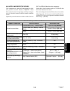
a. At ambients below 27_C(80_F), the condenser
fan will cycle o n/off depending on condenser
pressure and on/off times.
1. The condenser fan will start i f the condenser
pressure is greater than 200 psig OR the condenser
fan is OFF for more than 60 seconds.
2. The condenser fan will stop if the condenser
pressure is less than 130 psig AND the condenser
fan remains ON for at least 30 seconds.
b. At ambients above 27_C(80_F), condenser
pressure control (CPC) is disabled and the
condenser fan runs continuously.