


3-10T-268-07
CODE
#
DESCRIPTIONTITLE
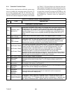
Inapplicable Functions Display ----------
Cd39
Secondary Return
Air Temperature
(Optional)
This code is only applicable to units without a DataCORDER, that are configured
to have four probes. If this is true, it will then display the current secondary return
air temperature.If the unit is configured with a DataCORDER, the Controller
function code Cd39 will display “----------,” and the display values for RRS will
appear on the DataCORDER function code dC2.
3.1.5 Controller Alarms
The alarm philosophy balances the protection of the
refrigeration unit and that of the refrigerated cargo. The
action taken when an error is detected always considers
the survival of the cargo. Rechecks aremade to confirm
that an error actually exists.
Some alarms requiring compressor shutdown havetime
delays before and after to try to keep the compressor on
line. An example is a low mains voltage, when the
voltage drops over 25%, an indication is given on the
display, but the unit will continue to run.
An alarm (See Table 3-4) is indicated by flashing an
alarm codeon thedisplaypanel,and forsomealarms,by
the alarm light illuminating.
When an Alarm Occurs:
S The red alarm light will illuminate for “20
series” alarms only.
S If a detectable problem is found to exist, its
alarm code will be alternately displayed with
the set point on the left display.
S The user should scroll through the alarm list
to determine what alarms exist or have
existed. Alarms must be diagnosed and
corrected before the Alarm List can be
cleared.
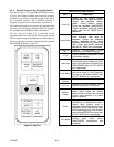
To Display Alarm Codes:
While in Set P oint Selection or Default Display mode,
press the ALARM LIST key. This accesses the Alarm
List Display Mode, which displays any alarms archived
in the Alarm Queue. The alarm list stores up to 16
alarms in the sequence in which they occurred. The user
may scroll through the list by depressing the UP
ARROW key. Depressing the DOWN ARROW key
allows the user to scroll backward through the list.
The left display will show “AL#,” where # is the alarm
number sequentially in the queue.
The right display will show:
S “AAXX” for an active alarm, where “XX” is
the alarm code. See Table 3-4, Controller
Alarm Indications.
S “IAXX” for an inactive alarm.
“END” is displayed t o indicate the end of the alarm list
if any alarms are active. “CLEAr” is displayed if all
alarms are inactive.
S The alarm queue may only be cleared if no
alarms are active, other than alarm code
AL51, and “CLEAr” is displayed.
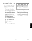
To Clear the Alarm List:
If all above conditions have been satisfied, e.g. no
alarms areactiveother than AL51, thealarm queuemay
be cleared.
S Press the ENTER key. The alarm list will
c l e a r a n d “ -- -- -- -- -- ” w i l l b e d i s p l a y e d .
NOTE
If the unit is configured for single evaporator
fan operation (refer to Table 3-1), and
troubleshooting alarms AL11 and AL12, be
aware that t he presence of 24 vac on the
evaporator fan motor internal protector safety
sense lines (MC6 and KB10) will indicate a
failure condition. This differs from most other
circumstances, whereby the absence of 24 vac
usually means an alarm condition is present.