


SECTION 6
6-19 T-268-07
(mountedtoinstrumentcase). Asingleprobeis attached
to the element (bulb) capillary which senses the
container return air temperature. If using two probes,
one probe will be attached to the supply air temperature
sensor.
In the event of a failure with the #344 test lead, other
instruments for checking bulb temperatures are:
Simpson Meter, CTC P/N 07-00013 or Robinair
Thermistor Temperature Tester, Model 12860:
A resistance thermometer with RCA lead and a
phono-plug ateachend maybe usedtocomparethebulb
temperature and the stylus indicated temperature on the
chart by inserting one end of the lead into the receptacle
provided on the controller and the other end in the
meter. Always check resistance thermometer before
using. (Refer to 6.19.b.)
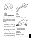
Ohmmeter:
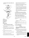
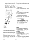
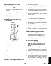
1. Place one probe of ohmmeter in the middle of the
receptacle provided on the chart platen (Figure 6-19).
Ground other probe to unit.
2. Note reading of meter and using Table 6-2, convert
resistance to temperature.
CAUTION
The inside mechanism of the control,
particularly the inside of the element
housing should never be oiled, however,
control mechanisms should be sprayed
periodically (every 60 days) with corrosion
inhibiting CRC 3-36a or 6-66 or LPS no. 2.
b. Checking Resistance Thermometer (Optional)
Calibrate the resistance thermometer by completely
filling a thermos container full of ice cubes or chipsand
filling the voids between the ice with plain water. Stir
the solution until the mixture registers 0 to0.3_C(32to
32.5_F), as indicated by a laboratory thermometer.
Immerse the resistance thermometer in the 0_C(32_F)
solution to check its accuracy at this temperature. It is
important that the recommended length of the check
probe is immersed so that it will accurately reflect
temperature. This measurement checks the test probe at
0_C(32_F) only. It is possible for the resistance
thermometer to be inaccurate at other temperatures.
Rezero check thermometer if necessary following
manufacturer’s instructions.
c. Checking the Recording Thermometer Bulb
Temperature
Checking temperature is accomplished by c omparing
the instrument’s indicated temperature(stylus) withthe
known temperature existing at the element sensing
bulb. To properly checkthe temperatureof therecorder,
the element sensing bulb should be stabilized at a
temperature of 0_C(32_F). This is accomplished by
using one of the two following methods, whichever is
more convenient.
Unit Running:
Place set point at 0_C(32_F). After unit has pulled
down tot his temperature, allowthe compressorto cycle
ON-OFF three to five times to be certain temperature
hasstabilizedat 0_C(32_F)asverifiedby theresistance
thermometer. If the temperature indicated by the
thermometer differs from 0_C(32_F) by more than
0.6_C(1_F) when compressor cycles off, rezeroing
must be performed.
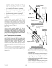
Unit Off:
Placethe recordingthermometer element (sensingbulb)
in 0_C(32_F) ice-water bath. Ice-waterbath is p repared
by filling an insulated container (of sufficient size to
completelyimmersebulb)withicecubesorchippedice,
filling voids between ice with water, and agitating until
mixture reaches 0_C(32_F) as shown by a laboratory
thermometer.
When the temperature at the element sensing bulb has
stabilized at 0_C(32_F), as shown by stable stylus
indication, comparethe temperatureindicated by stylus
withtemperatureshown byalaboratory thermometer.If
the two readings do not agree, the recording
thermometer should be rezeroed. (Refer to parag raph d. )
d. Rezeroing the Recording Thermometer
1. Be certain that the element bulb temperature has
stabilized at 0_C(32_F). Note the amount of
temperature difference between the test meter or
thermometer reading and the stylus indicated
temperature.
If the difference noted between the known element
temperature and indicated temperature is within
acceptable limits (0.3 of 0_C = 1/2_ of 32_F), do not
attempt to rezero. If more than 0.3_C (1/2_F) in
variation, carefully note the number of degrees.
2. If recording thermometer is found to require
rezeroing:
(a) Loosenset s crew(item 3, Figure 6-19) and zero
thermometer by turning pinion shaft (item 4).
Lengthening pinion shaft (counterclockwise)