


6-30T-268-07
circuits (refer to section 5). A description of the test
points follows:
NOTE
Use a digital voltmeter to measure ac voltage
between TP’s and ground (TP9), except for
TP8.
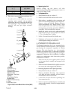
TP2
This test point enables the user to check if the internal
protector for the compressor motor (IP-CP) is open or
closed (and the Auto Transformer-IP if so equipped).
TP3
This test point enables the user to check if the optional
water pressure switch (WP) contact is open or closed.
TP7
This test pointenablest he userto checkif theController
relay (TS) contact is open or closed.
TP8
This test point enables the user to check the suction
modulation valve (SMV) current (amps), it is
represented bytwice thedc volts between TP8 and TP9.
TP9
This test point is the chassis (unit frame) ground
connection.
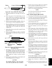
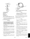
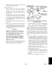
6.28 WATER-COOLED CONDENSER
The water-cooled condenser is of theshell and coil type
with water circulating through the cupro-nickel coil.
The refrigerant vapor is admitted to the shell side and is
condensed on the outer surface of the coil.
Rust, scale and slime on the water-cooling surfaces
inside of the coil interfere with the transfer of heat,
reduce system capacity, cause higher head pressures
and increase the load on the system.
By checking the leaving water temperature and the
actual condensing temperature, it can be determined if
the condenser coil is becoming dirty. A larger than
normal difference between leaving condensing water
temperature and actual condensing temperature,
coupled with a small difference i n temperature of
entering and leaving condensing water, is an indication
of a dirty condensing coil.
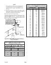
To find the approximate condensing temperature, with
the unitrunning inthe cooling mode,install agauge 0to
36.2 kg/cm@ (0 to 500 psig) on the compressor
discharge service valve.
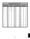
Example: Discharge pressure is 10.3 kg/cm@ (146.4
psig). Referring to Table 6-6 (R-134a
pressure-temperature chart), the 10.3 kg/cm@ (146.4
psig) value converts to 43_C (110_F).
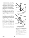
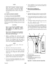
If thewater-cooled condenser isdirty, it may becleaned
and de-scaled by the following procedure:
a. Turn unit off and disconnect main power.
b. Disconnect water pressure switch tubing by
loosening the two flare nuts. Install one-quarter
inch flare cap on water-cooled condenser inlet tube
(replaces tubing flare n ut). De-s cale t ubing if
necessary.
What You Will Need:
1. Oakite composition No. 22, available as a powder
in 68 kg (150 lb) and 136 kg (300 lb).
2. Oakite composition No. 32, available as a liquid in
cases, each containing 3.785 liters (4 U.S. gallon)
bottles and also in carboys of 52.6 kg (116 lbs) net.
3. Fresh clean water.
4. Acid proof pump and containers or bottles with
rubber hose.
NOTE
When Oakite compound No. 32 is being used
for the first time, the local Oakite Technical
Service representative should be called in for
their suggestions in planning the procedure.
They will show you how to do the work with a
minimum dismantling of equipment: how to
estimate the time and amount of compound
required; how to prepare the solution; how to
control and conclude the de-scaling operation
by rinsing and neutralizing equipment before
putting it back intoservice. Their knowledgeof
metals, types of scale, water conditions and
de-scaling techniques will be highly useful to
you.
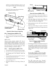
Summary of Procedure:
1. Drain water from condenser tubing circuit. Clean
water tubes with Oakite No. 22 to remove mud and
slime.
2. Flush.
3. De-scale water tubes with Oakite No. 32 to remove
scale.
4. Flush.
5. Neutralize.
6. Flush.