


SECTION 3
3-11 T-268-07
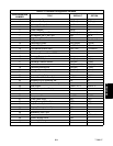
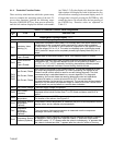
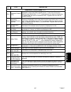
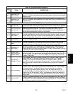
Table 3-4. Controller Alarm Indications
CODE
#
TITLE DESCRIPTION
MODEL 69NT40-511- 72
AL11
Evaporator Fan
Motor 1 Safety
Alarm 11 is triggered by the opening of the internal protector for evaporator fan
motor #1. This alarm will disable the probe check portion of defrost and the probe
diagnostic logic.
AL12
Evaporator Fan
Motor 2 Safety
Alarm 12 is triggered by the opening of the internal protector for evaporator fan
motor #2. This alarm will disable the probe check portion of defrost and the probe
diagnostic logic.
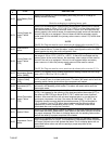
ALL MODELS
AL20
Control Circuit Fuse
Open (24 vac)
Alarm 20 is triggered by fuse (F3) opening and will cause the software shutdown
of all control units. This alarm will remain active until the 15 amp fuse is replaced.
AL21
Micro Circuit Fuse
Open (18 vac)
Alarm 21 is triggered by one of the fuses (F1/F2) being opened on 18 volts AC
power supply to the Controller. The suction modulation valve (SMV) will be
opened and current limiting is halted. The compressor will cycle. Temperature
control will be maintained by cycling the compressor.
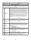
AL22
Evaporator Fan
Motor Safety
Alarm 22 is triggered by the opening of the evaporator motor internal protector.
This alarm will disable all control units until the motor protector resets. Also, refer
to code Cd29.If the unit is configured for single evaporator fan operation, alarm
AL22 will also activate if alarms AL11 and AL12 are active simultaneously.
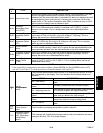
AL23
KA2--KB10 Jumper
Disconnected
Alarm 23 is triggered by a missing jumper wire. The alarm will stay active until the
jumper wire is reconnected.
AL24
Compressor Motor
Safety
Alarm 24 is triggered by the opening of the compressor motor internal protector.
This alarm will disable all control units except for the evaporator fans and will
remain active until the motor protector resets. Also, refer to code Cd29.
AL25
Condenser Fan
Motor Safety
Alarm 25 is triggered by the opening of the condenser motor internal protector
and will disable all control units except for the evaporator fans. This alarm will
remain active until the motor protector resets. This alarm is deactivated if the unit
is operating on water cooled condensing.
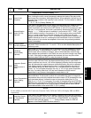
AL26
All Supply and
Return Air Control
Sensors Failure
Alarm 26 is triggered if the Controller determines that all of the control sensors
are out-of-range. This can occur for box temperatures outside the range of --50_C
to +70_C(--58_F to +158_F). This alarm triggers the failure action code set by
Function Code Cd29.
AL27
Probe Circuit
Calibration Failure
The Controller has a built-in Analog to Digital (A-D) converter, used to convert
analog readings (i.e. temperature sensors, current sensors, etc.) to digital
readings. The Controller continuously performs calibration tests on the A-D
converter. If the A-D converter fails to calibrate for 30 consecutive seconds, this
alarm is activated.This alarm will be inactivated as soon as the A-D converter
calibrates.
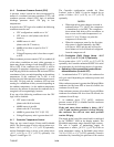
AL51 Alarm List Failure
During start-up diagnostics, the EEPROM is examined to determine validity of its
contents. This is done by testing the set point and the alarm list. If the contents
are invalid, Alarm 51 is activated.During control processing, any operation
involving alarm list activity that results in an error will cause Alarm 51 to be
activated.Alarm 51 is a “display only” alarm and is not written into the alarm list.
Pressing the ENTER key when “CLEAr” is displayed will result in an attempt to
clear the alarm list. If that action is successful (all alarms are inactive), Alarm 51
will be reset.
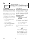
AL52 Alarm List Full
Alarm 52 is activated whenever the alarm list is determined to be full; at start-up
or after recording an alarm in the list. Alarm 52 is displayed, but is not recorded in
the alarm list. This alarm can be reset by clearing the alarm list. This can be done
only if all alarms written in the list are inactive.