


SECTION 6
6-21 T-268-07
4. If adjustment is required, loosen setscrew
(cross-recessed head). Using a 7 m m wrench, rotate
the adjustment screwclockwise toset thestylus 1to
2_C(1.8to3.6_F) higher than desired temperature.
5. Rotate the adjustment screw counterclockwise to
set the stylus about 0.5_C (0.9_F) higher than set
temperature. Rotate the chart by hand. The
indicated temperature should be 0_C(32_F).
c. Replacing Sensor Probe
1. Remove box from unit.
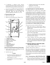
2. Remove nut and bushing (item 9, Figure 6-20).
1
2
3
4
9
5
6
7
8
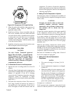
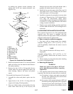
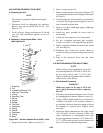
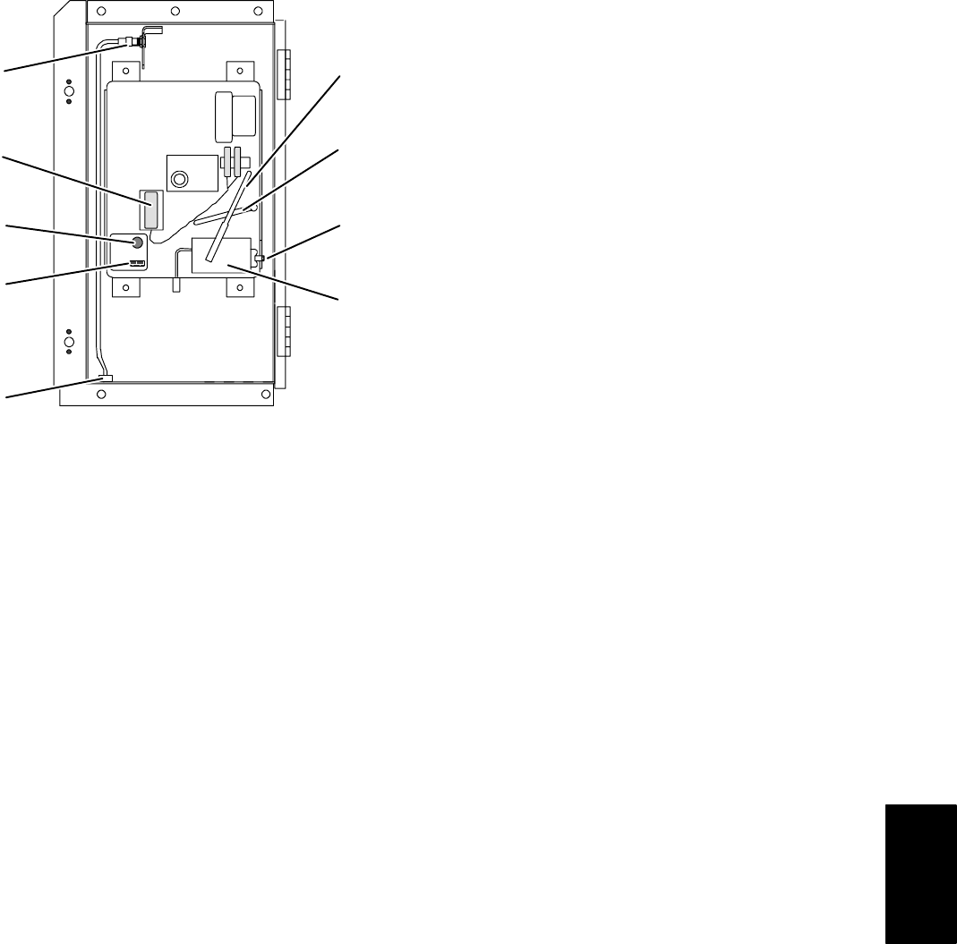
1. Voltage Indicator
2. Indicator Test Switch
3. Battery (“C” size, Alkaline)
4. Sensor Assembly
5. Stylus
6. Stylus Lifter
7. Setscrew (Adjustment)
8. Bulb and Mechanism
9. Bushing and Nut
Figure 6-20. Saginomiya Recording Thermometer
3. Install replacement probe and bushing. Seal with
silicone before securing to case.
4. Install box into unit.
NOTES
S One full turn with the adjustment screw
changes the indicated temperature by
approximately 5_C(9_F).
S Overtightening of setscrew may change set
temperature.
S Calibration should only be done when bulb
temperature is decreasing.
S DO NOT move stylus by hand.
6.21 MAINTENANCE OF PAINTED SURFACES
The refrigeration unit is protected by a special paint
system against the corrosive atmosphere in which it
normallyoperates.However,should thepaint system be
damaged, the b ase metal can corrode. In order to protect
the refrigeration unit from the highly corrosive sea
atmosphere, or if the protective paint system is
scratched or damaged, clean area to bare metal using a
wire brush, emery paperor equivalent cleaning method.
Immediately following cleaning, spray or brush on
zinc-rich primer. After the primer has dried, spray or
brushon finish coat of paint tomatchoriginal unitcolor.
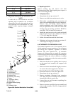
6.22 POWER AUTOTRANSFORMER (OPTIONAL)
If the unit does not start, check the following:
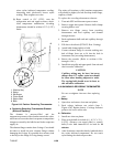
a. Make sure the 460 vac (yellow) power cable is
plugged into the receptacle (item 3, Figure 2-9) and
locked in place.
b. Make sure that circuit breakers CB-1 and CB-2 are
in the “ON” position. If the circuit breakers do not
hold in, check voltage supply.
c. There is no internal protector for this particular
transformer design, therefore, no checking of the
internal protector is required.
d. Using a voltmeter, and with the primary supply
circuit ON, check the primary (input) voltage (460
vac). Next, check the secondary (output) voltage
(230 vac). The transformer is defective if voltage is
not available.
6.23 SENSOR CHECKOUT PROCEDURE (AMBS,
DTS, RRS, RTS, SRS & STS)
An accurate ohmmeter must be used to check the
resistance values shown in Table 6-1.
Due to the variations and inaccuracies in ohmmeters,
thermometers or other test equipment, a reading within
2% of the chart value would indicate a good sensor. If a
sensor is defective, the resistance reading will usually
bemuchhigheror lowerthantheresistancevaluesgiven
in Table 6-1.
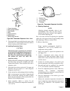
6.23.1 C hecking Sensor (RRS, RTS, SRS or STS)
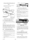
a. Place the sensor (sensing bulb) in a 0_C(32_F)
ice-water bath. The ice-water bath is prepared by
filling an insulated container (of sufficient size t o