


SECTION 2
2-9 T-268-07
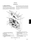
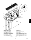
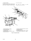
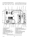
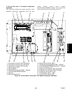
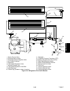
h. Control Box with a Two-Speed Compressor
(Optional)
The control box includes the manual switches, circuit
breaker(s), contactors, transformer, fuses, key pad,
display module, current sensor module,
Controller/DataCORDER module (See Figure 2-8),
and an optional remote m onitoring unit (CI).
CAUTION: DONOT MANUALLY
ENGAGE CONTACTORS
1
23
45
6
78
9
10
11
12
13
14
15
16
17
18
1. Compressor Contactor (CH) High Speed
2. Compressor Contactor (CL) Low Speed
3. Compressor Contactor (SC) Shorting
4. Heat Contactor (HR)
5. Display Module
6. Remote Monitoring Unit (RMU) -- Optional
7. Controller/DataCORDER Module
8. Key Pad
9. Start-Stop Switch (ST)
10. Manual Defrost Switch (MDS)
11. Remote Monitoring Receptacle (RM) -- Optional
12. Controller/DataCORDER Battery Pack -- Optional
13. Control Transformer (TR)
14. Evaporator Fan Contactor (EF) High Speed
15. Evaporator Fan Contactor (ES) Low Speed
16. Condenser Fan Contactor (CF)
17. Circuit Breaker (CB-1) -- 460V
18. Current Sensor Module (CS)
Figure 2-8. Control Box on Units with a Two-Speed Compressor (Optional)