


SECTION 6
6-9 T-268-07
123
4
5
6
78
10
11
12
13
14
15
9
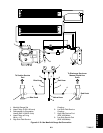
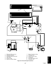
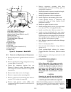
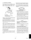
1. Discharge Valve Flange
2. High Side Pressure Connection
3. Low Side Pressure Connection
4. Suction Valve Flange (Refer to note #7)
5. Motor End Cover
6. Serial/Model No. Plate
7. Crankcase Heater (Optional)
8. Bottom Plate
9. Sight Glass
10. Oil Drain Plug
11. Bearing Head
12. Oil Pump
13. Oil Fill Plug (Refer to section 6.10)
14. Cylinder Head
15. Valve Plate
Figure 6-5. Compressor -- Model 06DR
6.7.1 Removal and Replacement of Compressor
a. Remove the protective guard from lower section of
the unit.
b. Remove all refrigerant using a refrigerant recovery
system. (Refer to section 6.3)
c. Locate the compressor junction box, see
Figure 6-5. Remove wiring. Disconnect wiring
from compressor terminals and removecompressor
junction box.
d. Remove bolts from service valve flanges.
e. Remove compressor plate mounting bolts.
f. Remove compressor and mounting plate. Refer to
section 2.2 for weight of compressor.
g. Remove high pressure switch (HPS) from
compressor and check operation of switch (refer to
section 6.12.2).
h. Remove compressor mounting bolts from
mounting plate and install mounting plate on
replacement compressor.
i. Install replacement compressor terminal wiring kit,
following instructions included with kit.
j. Install high pressure switch on compressor.
k. Install compressor and mounting plate in unit.
l. Connect junction box(es) to compressor and
connect all wiring per wiring diagram. Install
junction box cover(s).
m. Install new gaskets on service valves.
n. Install mounting bolts in service valves and torque
to a value of 2.77 to 4.15 mkg (20-30 ft/lb).
o. Install a new filter-drier. (Refer to section 6.11)
p. Attach two hoses (with hand valves near vacuum
pump) to the suction and discharge service valves.
Dehydrate and evacuate compressorto 500microns
(75.9 cm Hg vacuum = 29.90 inches Hg vacuum).
Turn off valves on both hoses to pump.
q. Fully backseat (open) both suction and discharge
service valves.
r. R emove vacuum pump lines.
s. Start unit and check refrigerant charge. (Refer to
section 6.6.1.)
t. Check moisture-liquid indicator for wetness.
Change filter-drier if necessary. (Refer to section
6.11)
u. Check compressor oil level per section 6.10. Add
oil if necessary.
6.8 COMPRESSOR DISASSEMBLY
WARNING
Before disassembly of the compressor make
sure to relieve the internal pressure very
carefully by slightly loosening the bolts on
both service valve flanges/blank valve pads,
then l ightly tap the center of the valve
flanges/pads with a lead hammer to break
the seal.
CAUTION
Removing the press-fit stator in the field is
not recommended. The rotor and stator are
a matched pair and should not beseparated.
When disassembling compressor, matchmark parts so
they may be replaced in their same relative positions.
(See Figure 6-5 compressor illustration.) Refer to