


6-4T-268-07
6.2 SUCTION AND DISCHARGE SERVICE
VALVES
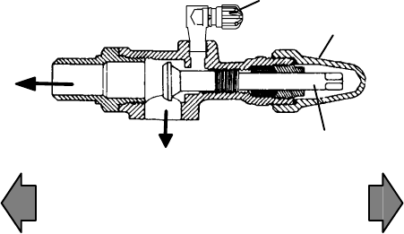
The suction and discharge service valves used on the
compressor are equipped with mating flanges for
connection to flanges on the compressor. These valves
are provided with a double seat and a gauge connection
which enable servicing of the compressor and
refrigerant lines.
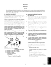
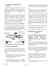
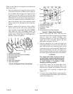
Turning the valve stem clockwise (all the way forward)
will frontseat the valve to close off the suction or
discharge line and open the gauge connection to the
compressor. See Figure 6-3. Turning the valve stem
counterclockwise (all t he way out) will backseat the
valve to open the suction or discharge line to the
compressor and close off the gauge connection.
With the valve stem midway between frontseated and
backseated positions, the suction or discharge line is
open to both t he compressor and the gauge connection.
For example, when connecting a manifold gauge to
measure suction or dischargepressure, thevalve stem is
fully backseated. Then, to measure suction or discharge
pressure, crack open the valves 1/4 to 1/2 turn.
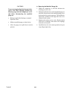
Gauge Connection
Valve Cap
Valve Stem
To Suction or
Discharge Line
Compressor
Valve
Frontseated
(clockwise)
Valve
Backseated
(counterclockwise)
Figure 6-3. Suction or Discharge Service Valve
6.3 PUMPING THE UNIT DOWN
To service the filter-drier, m oisture-liquid indicator,
expansion valve, suction modulation valve, suction
solenoid valve or evaporator coil, pump most of the
refrigerant into the condenser coil and receiver as
follows:
a. Backseat the suction and discharge valves (turn
counterclockwise) to close off gauge connections
and attach manifold gauges t o valves.
Refertosection6.1.a.
b. Allow the compressor to run 10 to 15 minutes
before frontseating the liquid linevalve. Then close
(front seat) the liquid line valve by turning
clockwise. St art the unit and run in a cooling mode.
Placestart-stopswitchinthe OFF positionwhenthe
unit reaches a positive pressure of 0.1 kg/cm@ (1.0
psig).
c. Frontseat (close) the suction service valve. The
refrigerant will be trapped between the compressor
suction service valve and the liquid line valve.
d. Before opening up any part of the system, a slight
positive pressure should be indicated on the
pressure gauge. If a vacuum is indicated, emit
refrigerant by cracking the liquid line valve
momentarily to build up a slight positive pressure.
e. When opening up the refrigerant system, certain
parts may frost. Allow the part to warm to ambient
temperature before dismantling. This avoids
internal condensation which puts moisture in the
system.
f. After repairs have been made, be sure to perform a
refrigerant leak check (section 6.4), and evacuate
and dehydrate the system (section 6. 5).
g. Check refrigerant charge (refer to section 6.6).
6.4 REFRIGERANT LEAK CHECKING
WARNING
Never mix refrigerants with air for leak
testing. It has been determined that
pressurized, air-rich mixtures of
refrigerants and air can undergo
combustion when exposed to an ignition
source.
a. The recommended procedure for finding leaks in a
system is with a R-134a electronic leak detector.
Testing joints with soapsuds is satisfactory only for
locating large leaks.
b. If the system is without refrigerant, charge the
system with refrigerant to build up pressure
between 2.1 to 3.5 kg/cm@ (30 to 50 psig). Remove
refrigerant cylinder and leak-check all connections.
NOTE
It must be emphasized that only the correct
refrigerant cylinder be connected to pressurize
the system. Any other gas or vapor will
contaminate the system, which will require
additional purging and evacuation of the
system.
c. Remove refrigerant using a refrigerant recovery
system and repair any leaks.