


3-30T-268-07
e. Display vs. Configuration Codes
TheDataCORDER contains twotypesofdisplay codes;
Display and Configuration. Display codes will display
parameter values, but will not let them be modified.
Configuration codes can be modified via the
interrogator or with the insertion of the common
configuration software card.
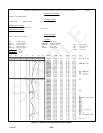
f. Data Recording Mode
The DataCORDER recording mode is labeled as
Standard. To seean example ofa reportusing astandard
configuration, see Figure 3-3.
Generic Mode:
The generic recording mode is used for special data
recordings. The user may select up to eight different
sensor readings. The sensors available for this type of
recording are listed below. Changing the configuration
to generic and selecting which sensors to record maybe
done via the Interrogation program.
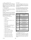
Configurable Generic Recording Options:
S Control mode
S Control temperature
S Frequency
S Humidity (Standard configuration: 6 or 64)
S Phase A current
S Phase B current
S Phase C current
S Mains voltage
S Suction modulation valve (SMV) percentage
S Discrete outputs (Bit mapped -- require
special handling if used)
S Discrete inputs (Bit mapped -- require special
handling if used)
S Ambient sensor (AMBS)
S Compressor suction sensor (CPSS)
S Compressor discharge sensor (CPDS)
S Return temperature sensor (RTS)
S Supply temperature sensor (STS)
S Defrost termination sensor (DTS)
S Discharge pressure transducer (DPT)
S Suction pressure transducer (SPT)
S Condenser pressure transducer (CPT)
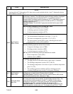
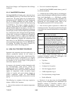
Standard Mode:
The standard recording mode allows the user to
configure the DataCORDER to monitor data using one
of seven standard configurations. The seven standard
configuration variables, with their descriptions, are
listed in Table 3-9.
The six thermistor inputs(supply, return,USDA #1,#2,
#3 and cargo probe) and the humidity sensor will be
DataCorder inputs. The three inputs will be read over a
network from the Controlled Atmosphere module.
In addition, if NO Controlleralarms are active, themost
recent active DataCORDER alarm will be displayed on
the Display Module alternately with set point.
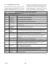
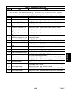
Table 3-9. DataCorder Standard Configuration
Standard
Configura -
tion
Description
2 sensors
(dCF02 = 2)
2 thermistor inputs(supply & return)
5 sensors
(dCF02 = 5)
2 thermistor inputs(supply & return)
3 USDA thermistor inputs
6 sensors
(dCF02 = 6)
2 thermistor inputs(supply & return)
3 USDA thermistor inputs
1 humidity input
9 sensors
(dCF02 = 9)
2 thermistor inputs(supply & return)
3 USDA thermistor inputs
* 3 Controlled Atmosphere inputs
1 humidity input
6 sensors
(dCF02 = 54)
2 thermistor inputs(supply & return)
3 USDA thermistor inputs
1 cargo probe (thermistor input)
7 sensors
(dCF02 = 64)
2 thermistor inputs(supply & return)
3 USDA thermistor inputs
1 humidity input
1 cargo probe (thermistor input)
10 sensors
(dCF02 = 94)
2 thermistor inputs(supply & return)
3 USDA thermistor inputs
* 3 Controlled Atmosphere inputs
1 humidity input
1 cargo probe (thermistor input)
* Not Available on models 69NT40-511 or
69NT40-521.
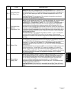
g. DataCORDER Alarm History List
The DataCORDER contains a buffer of up to eight
alarms. The list may be displayed by pressing the
ALARM LIST key. The alarm history keypad and
display processing will be the same as the Controller
module. The format of an alarm history display entry is
as follows: