


6-14T-268-07
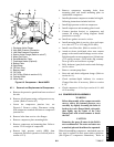
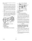
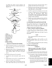
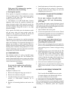
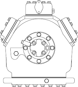
Figure 6-16. Compressor Oil Pump End View
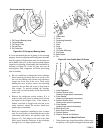
5. Align the gasket and install the eight capscrews in
the mounting flange. Refer to Table 6-5 for
applicable torque values.
6. Install rotor with key. Screw on equalizer tube and
lock screw assembly with lock washer and bend
over tabs of lock washer. Assemble suction strainer
to motor and cover and bolt cover to crankcase.
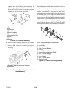
Assemble valve plates and gaskets. Assemble
cylinder heads and gaskets. Turn the shaft by hand
to see that it moves freely.
7. Install the oil suction screen, the oil suction screen
hold down plate and the bottom plate.
6.10 COMPRESSOR OI L LEVEL
CAUTION
Use only Carrier Transicold approved
Polyol Ester Oil (POE) -- Castrol-Icematic
SW20 compressor oil with R-134a. Buy in
quantities of one quart or smaller. When
using this hygroscopic oil, immediately
reseal. Do not leave container of oil open or
contamination will occur.
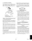
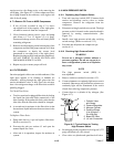
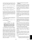
a. To Check the Oil Level in the Compressor:
1. Operate the unit in cooling mode for at least 20
minutes.
2. Check the front oil sight glass on the compressor to
ensure that no foaming of the oil is present after 20
minutes of operation. If the oil is foaming
excessivelyafter20 minutes ofoperation, checkthe
refrigerant system for flood-back of liquid
refrigerant. Correct this situation before performing
step 6.10.a.3.
3. Turn unit off to check the oil level. The correct oil
level range should be between the bottom to
one-eighth level of the sight glass. If the level is
above one-eighth, oil must be removed from the
compressor. To remove oil from the compressor,
follow step di n this section. If thelevel is below the
bottom of the sight glass, add oil to the compressor
following step b below.
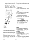
b. Adding Oil with Compressor in System
In an emergency where an oil pump is not available, oil
may be drawn into the compressor through the suction
service valve.
CAUTION
Extreme care must be taken to ensure the
manifold common connection remains
immersed in oil at all times. Otherwise air
and moisture will be drawn into the
compressor.
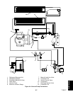
Connect the suction connection of the gauge manifold
to the compressor suction service valve port, and
immersethe common connection of the gaugemanifold
in an open container of refrigeration oil. Crack the
suction service valve and gauge valve to vent a small
amount of refrigerant through the common connection
and the oil to purge the lines of air. Close the gauge
manifold valve.
With the unit running, frontseat the suction service
valveandinduceavacuuminthe compressorcrankcase.
SLOWLY crack the suction gauge manifold valve and
oil will flow through the suction service valve into t he
compressor. Add oil as necessary.
Run unit for 20 minutes in cooling mode. Check oil
level at the compressor sight glass.
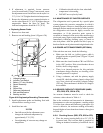
c. Adding Oil to Service Replacement
Compressor
NOTES
S The correct oil charge is 3.6 liters (7.6 U.S.
pints).
S Service replacement compressors are shipped
without oil.
S When first adding oil to the compressor, add
only three liters (6.3 pints) to the compressor.
Run the unit for 20 minutes in cooling mode.
Check the oil level in the compressor sight
glass. Add oil as necessary. This procedure is
designed to compensate for excess oil that
may have migrated with refrigerant to other
parts of the system during unit operation.
If compressor i s without oil:
If oil is present in the compressor, ensure that it is the
correct oil. Add oil (sections 2.2 and 6.10) through the