


2-6T-268-07
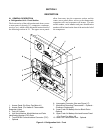
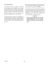
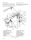
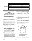
e. Receiver Section
The receiver section consists of quench expansion
valve, manual liquid line valve, filter-drier, receiver
with sight glass/moisture-liquid indicator, condenser
pressure transducer (CPT), fusible plug, suction
modulation valve, suction solenoid valve, and
discharge pressure regulator valve.
The supply temperature sensor (STS), supply recorder
sensor (S RS) a ndambient sensor (AMBS) are located at
the right side of the compressor.
17
1
2
10
5
6
13
14
11
12
9
8
7
15
16
3
4
18
19
1. Discharge Pressure Regulator Valve
2. Suction Modulation Valve (SMV)
3. Schrader Valve
4. Supply Air Thermometer Port -- Optional
5. Suction Solenoid Valve (SSV)
6. Quench Expansion Valve
7. Electro-Coated Modular Receiver
8. Sight Glass
9. Fusible Plug
10. Condenser Pressure Transducer (CPT) --
Located on back side of Receiver)
11. Sight Glass/Moisture Indicator
12. Filter-Drier
13. Manual Liquid Line Valve
14. Ambient Sensor (AMBS)
15. Supply Temperature Sensor (STS)
16. Supply Recorder Sensor (SRS)
17. High Pressure Switch (HPS)
18. Thermistor Sensor (CPDS)
19. Thermistor Sensor (CPSS)
Figure 2-5. Units with Receiver