


6-12T-268-07
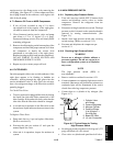
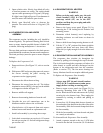
opening after the piston rings are compressed. A
piston ringcompresser will facilitateremoval. Each
piston pinis l ocked in placeby lock rings which are
snapped into grooves in the piston wall.
1
2
3
4
5
6
7
8
9
10
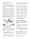
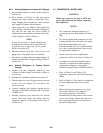
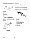
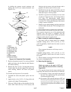
1. Capscrew
2. Cap
3. Crankshaft
4. Thrust Washer
5. Rotor Drive Key
6. Connecting Rod
7. Compression Ring
8. Piston
9. Pin
10. Retainer
Figure 6-11. Crankshaft Assembly
k. Since the stator cannot be replaced in the field, the
terminal plate assembly need not be disturbed
unless a leak exists or a terminal part requires
replacing.
1
2
3
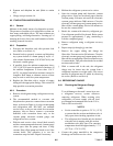
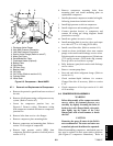
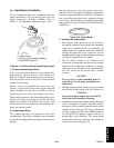
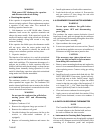
1. Equalizer Tube and Lockscrew Assembly
2. Lockwasher
3. Counterweight -- Motor End
Figure 6-12. Removing Equalizing Tube and Lock
Screw Assembly
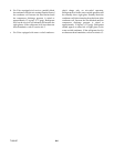
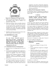
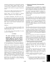
Disassemble and assemble the t erminal plate as shown
in Figure 6-13.
The terminal mounting plate assembly, as originally
installed, is assembled so as to leave a small space
between the outer terminal bushing and the surface of
the mounting plate. This is to provide further crush of
theterminalbushing incasealeakshould occur. Tostop
a leak, tighten the terminal bushing nut only enough to
stop the escape of gas. Do not tighten until the terminal
bushingis fl ush withthem ounting plate. Thetightening
torque used at the factory is 0.21 to 0.23 mkg (18 to 20
inchpounds)maximum toprevent damageto theplastic
parts.
12
11
10
9
7
5
3
1
2
4
6
8
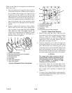
6
NOTE: Parts shown are for one terminal.
1. Terminal Bushing Nut
2. Lock Washer
3. Terminal Washer
4. Outer Terminal Bushing
5. O-Ring
6. Terminal Bushing Washers (Grey)
7. Terminal Bushing Washers (Red)
8. Inner Terminal Bushing
9. Terminal Mounting Plate
10. Cover Gasket
11. Inner Terminal Block
12. Terminal Screw
Figure 6-13. Terminal Mounting Assembly