


6-22T-268-07
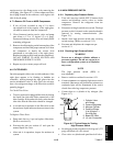
completely immerse bulb) with ice cubes or
chipped ice, then filling voids between ice with
water and agitating until mixture reaches 0_C
(32_F) measured on a l aboratory t hermometer.
b. Start unitand check air temperature/datareadout on
the control panel. The reading should be 0_C
(32_F);ifi t isnot, continue ontothefollowingstep.
c. Turn unit OFF and disconnect power supply.
d. Refer to section 6.27 for removal of the Controller
module.
RTS or STS:
Using the plug connector marked “EC” that is
connected to the Controller module. Locate the wires
marked RTS or STS, depending on which sensor needs
to be replaced. Follow that wire to the connector and
using the pins of the plug, measurethe ohms resistance.
Readings are shown in Table 6-1.
RRS or SRS:
Using the plug connector marked “EC” that is
connected to the Controller module. Locate the wires
marked RRS or SR S, depending on which sensor needs
to be replaced. Follow that wire to the connector and
using the pins of the plug, measurethe ohms resistance.
Readings are shown in Table 6-1.
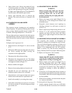
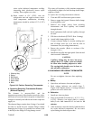
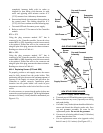
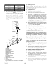
6.23.2 R eplacing Sensor (STS and SRS)
To properly position a unit supply sensor, the sensor
must be fully inserted into the probe holder. This
positioning will give thesensor the optimum amount of
exposure to the supply air stream, and will allow the
Controller to operate correctly. Insufficient probe
insertion into the probe holder will result in poor
temperature control due to the lack of air flow over the
sensor.
It is also necessary to ensure that the probe tip does not
contactthe evaporatorbackpanel. Thedesignminimum
clearance of 6 mm (1/4 inch) should be maintained (see
Figure 6-21).
Cap and Grommet
Assembly
Probe
Holder
Unit Frame
Evaporator
Back Panel
6mm
(1/4 inch)
Supply Sensor
Supply
Air
Stream
Sensor
Wires
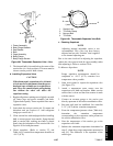
Cap and Grommet
Assembly
Probe
Holder
Supply Sensor
Sensor
Wires
OLD STYLE PROBE HOLDER
NEW STYLE PROBE HOLDER
Supply
Air
Stream
Evaporator
Back Panel
6mm
(1/4 inch)
Figure 6-21. Supply Sensor Positioning
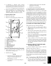
a. Turn unitpower OFF and disconnect powersupply.
b. Removeand save anycover (ifpresent) over wiring
and probe holder.
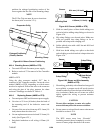
c. Cutcable5cm (2 inches)fromshoulderofdefective
sensor and discard the defective probe only. Save
cap and grommet assembly for reuse on the
replacement probe. Do not cut the grommet.
d. Cut onewireof existingcable 41mm (1-5/8inches)
shorter than the other wire.
e. Cut one replacement sensor wire (opposite color)
back 41 mm (1-5/8 inches). (See Figure 6-22.)