


6-20T-268-07
raises stylus indicated temperature reading;
shortening shaft (clockwise) lowers stylus
reading. Then retighten set screw.
(b) Reset control at 0_C(32_F), start the
refrigeration unit and repeat accuracy check.
After temperature stabilization, recording
thermometer should be within 0.3_C (1/2_F)
limits.
3
4
1
2
5
6
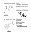
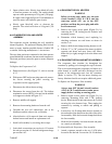
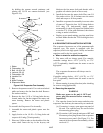
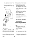
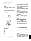
1. Wind-up Key
2. Stylus
3. Set Screw
4. Pinion Shaft
5. Stylus Lifter
6. Bulb
Figure 6-19. Partlow Recording Thermometer
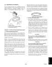
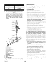
e. Replacing Recording Thermometer Element
(Bulb and Capillary)
The element is mercury-filled and the
temperature-pressure of theelement controls the stylus,
whichmoves acrossthe charti n responsetotemperature
changes as sensed by the bulb located in the evaporator
supply air.
The element flange contains three O-rings. Care should
be taken to install the new element flange without
damaging the O-rings. It is possible for a mercury leak
to develop at the flange if O-ring damage occurs.
The stylus will continue to fall (container temperature
will actually be higher) if a l eak develops in the flange,
capillary or bulb.
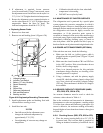
To replace the recording thermometer element:
1. Turn unit OFF and disconnect power source.
2. Remove upper back panel. Remove bulb clamps
securing bulb to unit.
3. Remove two flange screws from recording
thermometer and feed capillary and element
through the unit.
4. Push replacement bulb e nd and capillary through
the unit.
5. Fill slots with silastic (RTV432, Dow Corning).
6. Attach bulb clamps tightly to bulb.
7. Connect element flange to recorder making sure
hub of flange faces out to fit into the hole in
instrument case (recording thermometer).
8. Rezero the recorder. (Refer to sections 6.19.a.
through 6.19.d.)
9. Install inlet airgrille and upper panel. Start unit and
check recorder calibration.
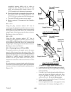
CAUTION
Capillary tubing may be bent, but never
sharper than 1/2” radius; extra care should
be taken when bending adjacent to welds.
The sensing bulb should never be bent, as
this will affect calibration.
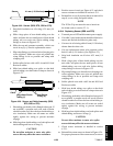
6.20 SAGIN OM IYA RECOR D IN G THE R M OME TER
NOTE
Do not overtighten chart nut after replacing
chart.
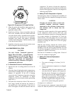
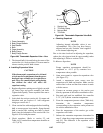
a. Battery
1. Open door and remove chart nut and platen.
2. Push voltage indicator test switch (item 2,
Figure 6-20). Replace battery if voltage indicator
points to t he red or white zone.
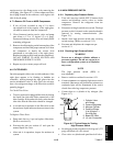
b. Calibration
1. Install new chart on platen.
2. Place recorder bulb in ice bath (0 ¦ 0.2_C=32¦
0.35_F ). (Remove rear upper panel to remove
bulb.) Leave bulb immersed in ice bath for 10
minutes.
3. After10 minutes, rotate the chart byhand andcheck
the stylus indicated temperature. Do not touch
stylus during the checkout procedure.