


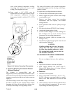

6-28T-268-07
NOTE
Suction pressure must be 0.5 kg/cm@ (6 psig)
below valve maximum operating pressure
(M.O.P.). Example: if valve rated at 55 MOP,
suction pressure must be below this MOP.
Recommended pressure is below 3. 44 kg/cm@
(49 psig).
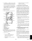
6.27 CONTROLLER/DATACORDER
a. Handling of Controller/DataCORDER
Theseguidelines shouldbe followed when handling the
Controller/DataCORDER module. These steps should
be implemented when replacing the module, when
doing anyarcwelding onthe unit,or when service to the
refrigeration unit requires handling and removal of the
Controller.
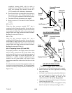
CAUTION
Remove Controller/DataCORDER module
and unplug all connectors before
performing any arc welding on any part of
the container.
Do not remove wire harnesses from m odules
unless you are grounded to the unit frame
with a static safe wrist strap.
1. Obtain a grounding wrist strap and a static
dissipation mat. The wrist strap, when properly
grounded, will dissipate any potential buildup on
the body. The dissipation mat will provide a
static-free work surface on which to place and/or
service the Controller/DataCORDER module.
NOTE
Use a dissipation mat, order CTD P /N
07-00277-00.
2. Disconnect and secure power to the unit.
3. Place strap on wrist and attach the ground or clip
end of the wrist strap to any exposed unpainted
metal area on the refrigeration unit frame (bolts,
screws, etc.).
4. Carefully remove the Controller/DataCORDER.
Do not touch any of the electrical components if
possible. Place the module on the static mat.
5. If you are servicing the refrigeration unit, you are
free to remove theground strap from yourwrist and
complete your work.
6. Upon completion of your service work, put the
wrist strap back on, and re-install the module into
the refrigeration unit.
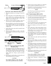
b. Removing and Installing the
Controller/DataCORDER Module
Removal:
1. Disconnect all front wire harness connectors (MA,
MB, MC, KA & KB) and move wiring out of way.
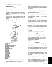
2. Loosen one mounting screw (see Figure 6-31, item
1)andpull outthetop ofthemodule(item2).Liftup
and out.
3. Turning the module around will give access to the
two back connectors (EC) which can be
disconnected. Remove module.
4. RemovethenewController/DataCORDERmodule
from its packaging and install it in the refrigeration
unit. Place the old module into the same packaging
that accompanied the new module. Make sure that
you packageitintheexact mannerthat youreceived
it.
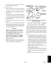
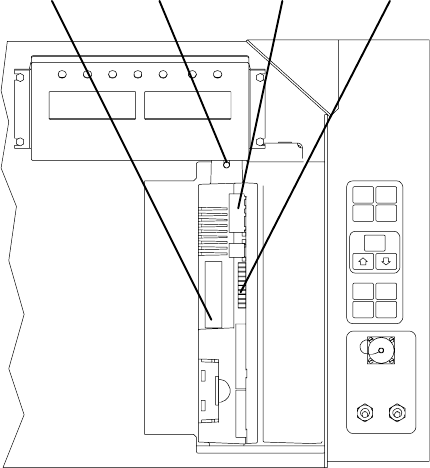
1234
1. Mounting Screw
2. Controller/DataCORDER Module
3. Test Points
4. Controller/DataCORDER Software
Programming Port
Figure 6- 31. C ontrolle r side of the Control Box