


6-10T-268-07
Table 6-4 and Table 6-5 for compressorwearlimits and
bolt torque values.
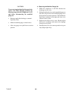
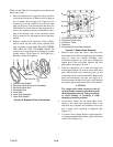
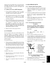
a. Place the compressor i n a position where it will be
convenient to drain the oil. Remove the oil plug on
the oil pump inlet passage (see Figure 6-8 for
location) to vent the crankcase. Loosen the drain
plug (see Figure 6-5) in bottom plate and allow the
oil to drain out slowly. R emove the plug slowly to
relieve any crankcase pressure. Some units have a
plug in the bottom center of t he crankcase which
may be removed for draining the motor end more
quickly.
b. Remove cylinder head capscrews. If t he cylinder
head is stuck, tap the center of the cylinder head
with a wooden or lead mallet. DO NOT STRIKE
THE SIDE OF THE CYLINDER HEAD! Be
careful not to drop the head or damage the gasket
sealing surface. (See Figure 6-5 and Figure 6-6.)
Remove cylinder head gasket.
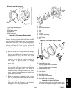
12 3 4 5 7
6
Jack here
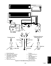
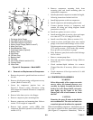
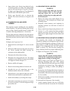
1. Cylinder Head Gasket
2. Discharge Valve Screw and Lockwasher
3. Discharge Valve Stop
4. Discharge Valve
5. Valve Plate
6. Valve Plate Assembly
7. Valve Plate Gasket
Figure 6-6. Exploded View of Valve Plate
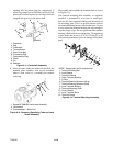
1
2
3
4
5
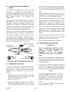
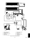
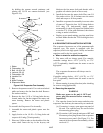
1. Oil Pressure Relief Valve
2. Oil Return Check Valve
3. Oil Suction Tube
4. Capscrew
5. Connecting Rod and Cap Assembly
Figure 6-7. Bottom Plate Removed
c. Remove valve stops and valves. After they have
beenremoved, freethevalve platefrom thecylinder
deck by using t he outside discharge valve
hold-down capscrew as a jack screw through the
tapped hole of the valve plate. Remove the valve
plate ga sket, see Figure 6-6, item 7.
d. Turn the compressor on its side and remove the
bottom plate and the oil suction screen hold down
plate. Match mark each connecting rod cap and
connecting rod for correct reassembly. Remove the
bolts and connecting rod caps (see Figure 6-7).
Push thepistonrods upasfarastheywillgo without
having the piston rings extend above the cylinders.
CAUTION
The copper tube which connects to the oil
suction strainer extends out the bottom with
the bottom plate removed. Take precautions
to avoid b ending or breaking it while
changing crankcase positions.
e. If necessary, remove the oil return check valve.
Inspect it for check valve operation (flow in one
direction only). R eplace the assembly with a new
unit if check valve operation is impaired. (See
Figure 6-7.)
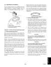
f. To remove the oil pump. Remove eight capscrews,
oil pump bearing head assembly, gasket and thrust
washer.(SeeFigure6-8.)