


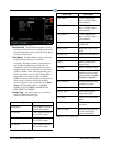
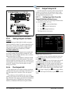
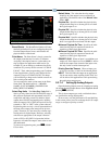
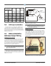

Figure 9-12 - Digital Output Screen
9-14 • E2 RX/BX/CX I&O Manual 026-1614 Rev 4 5-JAN-2013
Board/Point # The Board/Point Number will auto-
matically be defined if you are configuring the point
from
the Output Status screen, and indicates the
physical address of the board.
Point Name The Point Name is simply a name for
the output
point that may be used as a reference.
Assigning a descriptive name to a point makes set-
ting up outputs for applications much easier. For
exam
ple, if you are setting up condenser fan #3 for
condenser #2, you may choose to name it “CND #2
FAN #3”. Then, when programming your Condenser
Control application, you may easily define the fan
output by tying it to CND #2 FAN #3. This keeps
you from having to keep track of which contacts are
tied to which point numbers.
You are required to enter a point name in the Point
Name
field. The default name is “:{BOARD
NAME}:{UNIT NUMBER}:{BOARD NUM-
BER}:{POINT NUMBER}”.
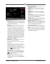
Select Eng. Units The Select E
ng. Units field is
where you may select how the ON and OFF states of
this point are displayed and represented in the E2’s
setup fields and status screens. By default, digital
outputs have ON-OFF engineering units, meaning
when the output is ON or OFF, the input will be rep-
resented as “ON” or “OFF” in the system software.
Engineering units are only a visual representation of
the state of
the output point (energized or de-ener-
gized). Therefore, it is not necessary to define engi-
neering units for digital inputs. However, selecting
uni
ts that are appropriate to the output’s function
(such as BYP or NO_BYP for inputs that initiate
bypasses) will make the output’s state easier to read
and understand.
To choose an engineering unit, press (LOOK
UP) to select.
Default Value The value that the relay output
shou
ld go to if the output is not associated to an
application. The default value of the Default Value
field is OFF.
Physical On Specifies whether the physical relay
ou
tput should energize or de-energize its coil when
the logical output is on.
Physical Off Specifies whether the physical relay
ou
tput should energize or de-energize its coil when
the logical output is off.
Physical Null Specifies whether the physical relay
ou
tput should energize or de-energize its coil when
there is no application associated with the output.
Minimum Physical On Time Specifies the mini-
mum time the physical output must remain on
reg
ardless of the logical output state.
Minimum Physical Off Time Specifies the mini-
mum time the physical output must remain off
reg
ardless of the logical output state.
PRIORITY OVR When an input is overridden to an
ou
tput cell. If this input is not set to NONE, it will be
used for the output value instead of the input value,
but only for the override timeout period.
Priority Override Timeout When an input goes
on
it will override to a value for the timeout period.
INPUT This field links the output to an application.
Y
ou do not need to enter anything in this field. You
will be able to link applications to this point during
the application setup process.
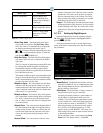
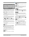
9.2.7.4 Setting Up Analog Outputs
Open the Analog Output screen by selecting an Analog
(A) output from the Output Status screen Figure 9-10 and
pressing (S
ETUP).
This is where output types, units, and default values
are specified for analog output points
.
In most cases, only the point name will need defining
in
this screen, unless you wish to change the 0-10V output
range or configure a priority override.