


11-48 • E2 RX/BX/CX I&O Manual 026-1614 Rev 4 5-JAN-2013
adjustment.
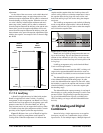
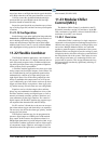
As the value of the reset sensor varies within the mini-
mum and maximum range, an equivalent portion of the
max
imum setpoint adjustment will be added or subtracted
from the heating or cooling setpoint. When the reset sen-
sor value is directly in between the minimum and maxi-
mum range values, nothing will be added or subtracted
from
the setpoint. Between the halfway point and the min-
imum value, part of the setpoint adjustment will be sub-
tracted from the setpoint. Between the halfway point and
the
maximum value, part of the setpoint adjustment will be
added to the setpoint. An example of this is shown in Fig-
ure 11-28.
Figure 11-28
- Setpoint Reset Diagram
MIN
RANGE
MIDPOINT
MAX
RANGE
ADDSUBTRACT
+0
RESET
SENSOR
RANGE
SET
POINT
CHANGE
MAX
CHANGE
MAX
CHANGE
11.17.5 Lead/Lag
A Heat/Cool application may be linked with another
Heat/Cool application in what is called a “Lead/Lag”
arrangement. In this arrangement, one Heat/Cool is desig-
nated as the Lead loop and used a
s the primary space tem-
perature control device. The other Heat/Cool, the Lag
loo
p, becomes active only to support the Lead loop when
it is unable to keep the space temperature within a certain
proximity of the setpoint (called the setpoint delta).
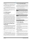
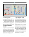
Figure 11-29 shows how a pair of Heat/Cool applica-
tions using a Lead/Lag arrangem
ent would operate in
Cooling mode. When the temperature is in between the
setpoint and the setpoint delta, the Lead loop alone will
control cooling. However, when the temperature is above
the setpoint delta, the Lag loop will come on-line, and
both Lead and Lag loops will work to bring the tempera-
ture down.
The Lead/Lag arrangement work
s similarly in Heating
mode, except that the setpoint delta is below the Heating
setpoint, and Lead and Lag are both on when the tempera-
ture is below the setpoint delta.
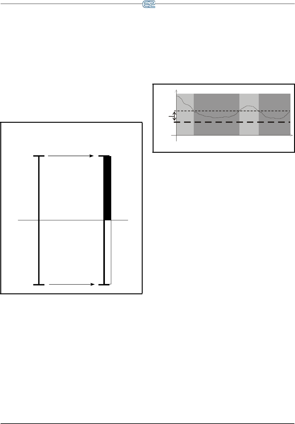
Figure 11-29 - Lead/Lag Arrangement
SETPT
DELTA
SET POINT
LEAD AND
LAG ON
LEAD AND
LAG ON
LEAD ON ONLY LEAD ON ONLY
TEMPERATURE
TIME
26512037
Heat/Cools in a Lead/Lag arrangement take turns act-
ing as the Lead loop. The user designates the ma
ximum
amount of time a Heat/Cool will act as a Lead loop; after
this duration, the current Lead loop will switch places with
its Lag loop.
Lead/Lag arrangements only work when
both Heat/
Cools are in Occupied mode.
Dehumidification control uses the AHU’
s existing cool
stages (and a separate dehumidification device such as a
desiccant wheel, if available) to remove moisture from the
air.
The dehumidification s
etpoint is placed at the 0% end
of the dehumidification PID throttling range. In other
words, the dehumidification output will start at 0% when
the humidity is equal to the setpoint and increase to 100%
when the humidity is equal to or above the setpoint plus
the throttling range.
The dehumidification output percentage is used much
li
ke a heating or cooling output percentage is used in Tem-
perature Control. The percentage repres
ents the percent-
age of total dehumidification capacity available to the
AH
U (including cool stages and other dehumidification
devices).
11.18 Analog and Digital
Combiners
Instead of using a single output source as an applica-
tion input, you may use a combination of up to sixteen
in
put sources. To use multiple inputs, a Multiple Input cell