


The 16AI, 8IO, and MultiFlex Inputs Input and Output Setup • 9-1
9 Input and Output Setup
9.1 The 16AI, 8IO, and
MultiFlex Inputs
9.1.1 Connecting Sensors to Input
Boards
There are five I/O Network boards that may accept
inputs: the MultiFlex, the 16AI, the ARTC, and the 8IO
Combination Input/Output Board. Wiring an input to these
boards requires three steps:
1. Connect the sensor’s signal wires to the two ter-
minals of an input point.
2. Set the input type dip switch that corresponds to
the point
being connected.
3. If necessary, connect t
he power lead of the sensor
to one of the 5V or 12V power terminals.
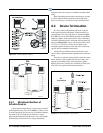
9.1.1.1 Wiring
MultiFlex Boards
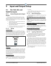
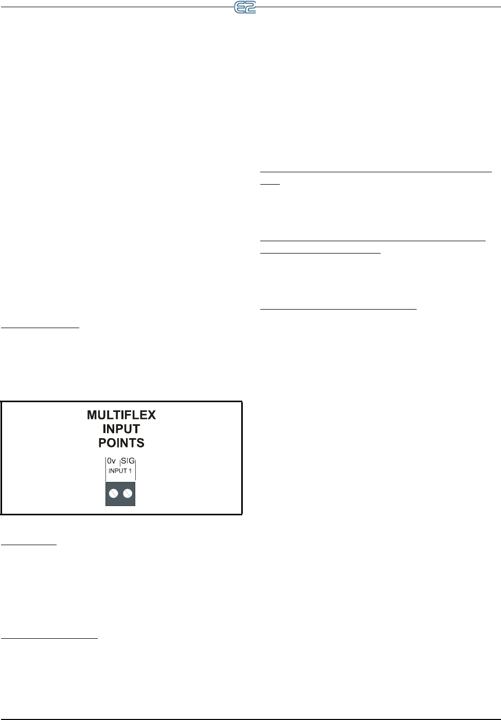
An input point connector on a MultiFlex, 16AI, and
16AIe board consists of two terminals, as shown in Figure
9-1. One of these terminals, labeled
“SIG”, reads the sig-
nal from the sensor, while the other, labeled “0v” is where
sensor
’s ground and/or cable shield wire is connected.
Figure 9-1
- Input Board Points
16AI Boards
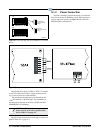
On a 16AI, terminals are numbered 1-32, starting with
the first terminal of point 1 and ending with the last termi-
nal of point 16. The even-numbered terminals of a 16AI
are always
where the signal voltages are connected. The
sensor grounds and cable shields are connected to the odd-
numbered terminals.
8IO and ARTC Boards
On an 8IO board, the two terminals of every point are
labeled “-” or “+”. The ground wire is always connected to
the “-” terminal, and the signal wire is connected to the
“+” terminal.
On the ARTC board, the input and output points are
predefined and are
labeled accordingly.
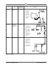
9.1.1.2 Sensor Wiring Types
Specific wiring types are required for each type of sen-
sor used with E2.
All Analog Temperature Sensors and Air Flow Sen-
sors
Temperature and air flow sensors are to be wired with
shielded, 2 conductor, at least 22 GA wire (Belden # 8761
or equivalent).
All Pressure Transducers, Humidity Sensors, and
Refrigeration Transducers
Pressure and refrigeration transducers and humidity
sensors are to be wired with shielded, 3 conductor, at least
22 GA wire (Belden #8771 or equivalent).
Dewpoint and Light Level Sensors
These sensors are to be wired with shielded, 4 conduc-
tor at least 22 GA wire (Belden # 8729 or equivalent).
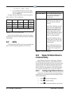
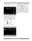
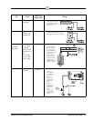
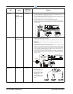
9.1.1.3 Input Type Dip Switches
An input type dip switch must be set for each input
point. Input type dip switches are located in the switch
banks labeled S1 and S2 on the MultiFlex, 16AI, and
switch bank S4 on the 8IO.
The input type dip switch tells the input board whether
or not
the sensor connected to the point requires a DC sup-
ply voltage in order to operate. If the sensor requires DC
vo
ltage, the dip switch should be set to the DOWN posi-
tion. If the sensor does not require power, or if it uses AC
po
wer, the dip switch should be set to the UP position. Dip
switches for unused points should be set to the UP posi-
tion.
The dip switch positions for each specific s
ensor type
is shown in Figure 9-2.