6-4 • E2 RX/BX/CX I&O Manual 026-1614 Rev 4 5-JAN-2013
Dip switch 8 controls the baud rate at which the Gate-
way communicates with the other devices
on the Receiver
Bus Network. This baud rate may only be set to either
9600 baud (switch DOWN) or 19200 baud (switch UP).
All Gateways and receivers on the Receiver Bus Network
must have the same baud rate dip switch setting. It is rec-
ommended you use 9600 baud as the Receiver Bus Net-
work baud rate.
Baud Rate for the 8IO, 8DO, and ARTC
There are three I/O devices that do not have baud rates
determined by dip switches. They are as follows:
1. The 8IO -
this board automatically detects the
baud rate being used by the I/O devices on the
network, and adjusts to match their baud rate.
2. Th
e 8DO - this board automatically detects the
baud rate being used by the I/O devices on the
network, and adjusts to match their baud rate.
3. T
he ARTC - this board is fixed at 9600 baud.
Baud Rate for MultiFlex Boards
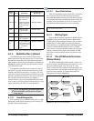
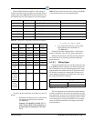
On all MultiFlex boards, switches 6 and 7 on S3 are
used to set the baud rate. To communicate at 9600 baud,
set switch #6 to the UP position and #7 to DOWN. For
19200 baud, set switch #6 to the DOWN position and #7
to UP.
Baud Rate for the MultiFlex ESR
Set the baud rate on the MultiFlex ESR board by set-
ting switches 6 and 7 on the network address terminal
(labeled S1).
To communicate at 9600 baud, set switch #6 to the UP
posit
ion, and switch #7 to DOWN. For 19200 baud, set
switch #6 to the DOWN position and switch #7 to UP.
(Currently, 9600 baud is recommended).
Recommended Baud Rate
The baud rate should be set to 9600 baud in all cases.
6.1.8 Setting the Terminating and
Biasing Jumpers
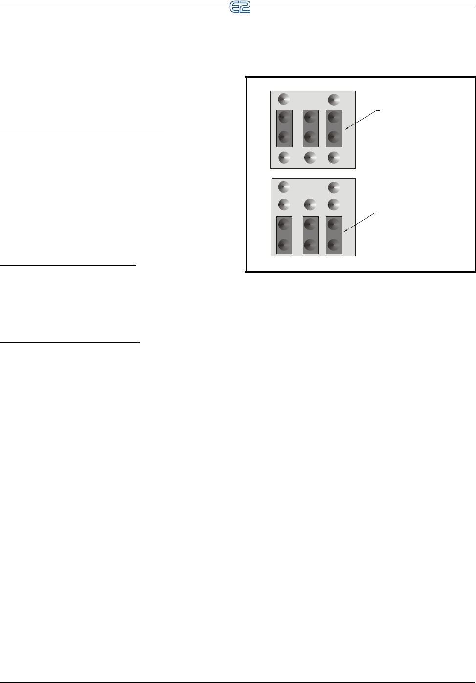
The I/O Network connector, for all I/O boards and the
E2, has a set of three terminating jumpers. They are the
jumpers positioned closest to the I/O Network connector.
The E2 has jumpers next to each of the COM ports that
can be configured as an I/O network (COM2, COM4, and
COM6).
The purpose of the jumpers is to provide network ter-
mination resistance and network biasing to the two ends,
or
termination points, of the daisy chain. One device at the
beginning and one device on the end must be terminated
and biased by placing all three jumpers in the UP or I/O
position. All other devices on the daisy chain must have all
three jumpers set to the DOWN or NO position.
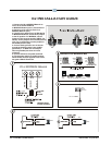
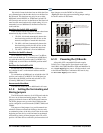
Figure 6-2 shows the proper terminating jumper settings
for the E2 and for all I/O boards.
Figure 6-2
- I/O Network Termination Jumper Settings
THE TERMINATING JUMPERS MUST
BE IN THE UP OR I/O POSITION IF AT THE
BEGINNING OR END OF THE NETWORK.
THE TERMINATING JUMPERS MUST
BE IN THE DOWN OR NO POSITION IF NOT AT
THE BEGINNING OR END OF THE NETWORK.
I/O BOARD AND E2 TERMINATING JUMPERS
I/O
NO
I/O
NO
6.1.9 Powering the I/O Boards
All models of E2-compatible I/O boards require
24VAC Class 2 input power. Some boards such as the
16AI, 8RO, 4AO, 8DO, MultiFlex ESR, and MultiFlex 16
use a center-tapped power source. All other models, such
as the 8IO and MultiFlex Combination I/O boards, may
use non-center tapped power sources.


