12-2 • E2 RX/BX/CX I&O Manual 026-1614 Rev 4 5-JAN-2013
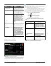
Power Monitoring Section
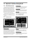
In the lowest left-hand corner of the BX Home screen
is the power monitoring section, containing active KW
and average power information.
Light Schedules Section
In the center of the BX Home screen is ON and OFF
status information for light schedules.
Air Handling Units Section
Located at the top right-hand corner of the BX Home
screen, the AHU section shows the number of AHUs, tem-
perature, state, and ASP information for each.
Zones Section
Directly below the AHU section is the Zones section,
which shows the number of zones, temperature, whether
or not the application is in occupied mode, CSP and HSP.
Sensor Control Section
Sensor Control is at the bottom right-hand corner of
the BX Home screen and contains analog and digital sen-
sors, value, command, and status information.
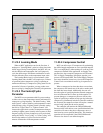
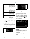
12.1.3 CX Home Screen
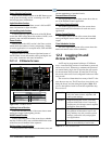
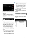
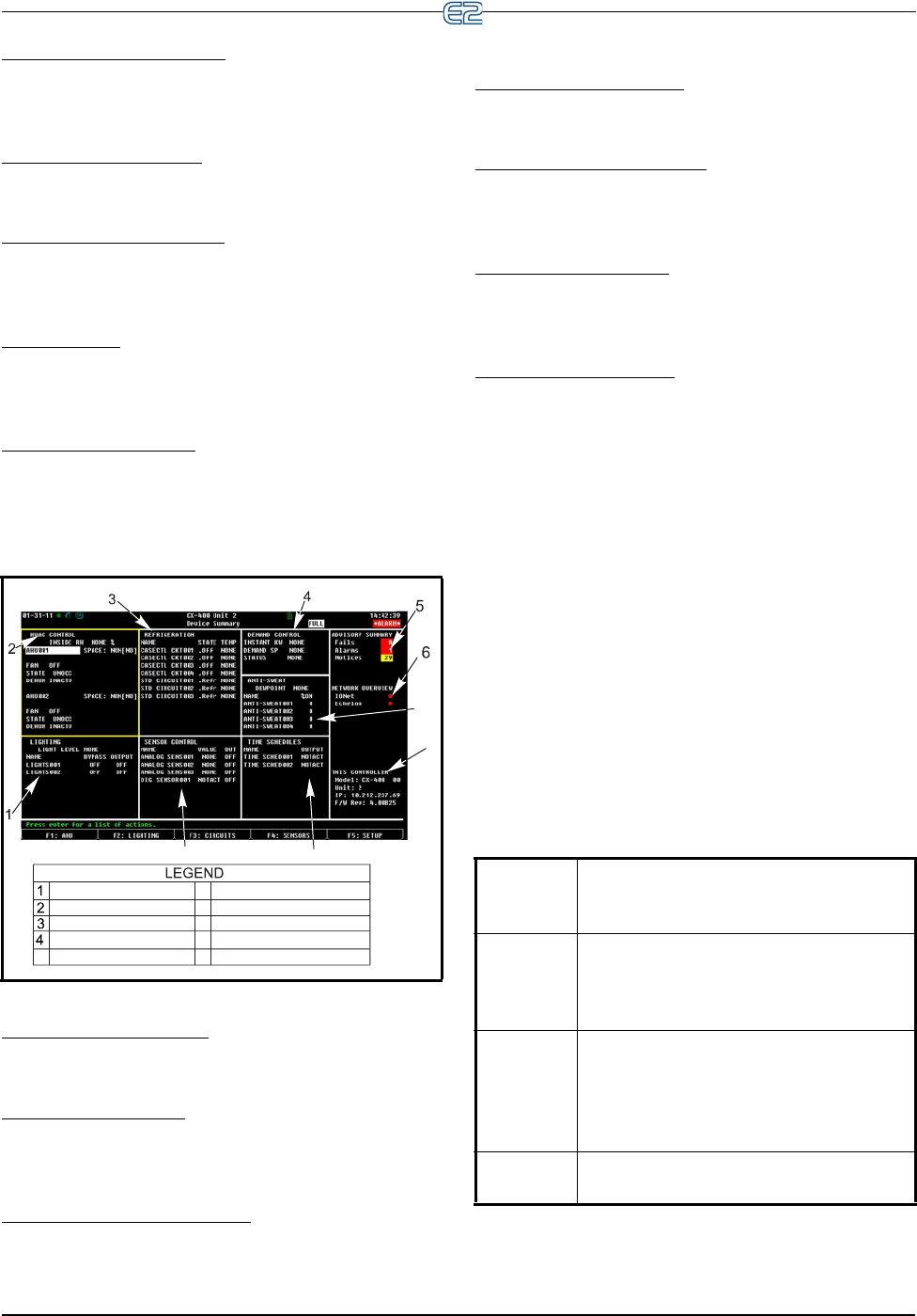
Figure 12-3 - CX Home Screen
HVAC Control
Refrigeration
Lighting
Demand Control
Network Information
Anti-Sweat
Controller Information
7
8
9
10
Advisory Information
Sensor Control
5
6
7
8
10
9
Time Schedules
Lighting Control Section
The lower left-hand corner of the screen shows name
and bypass output for the lighting circuits.
HVAC Control Section
The top left-hand corner of the screen shows whether
the fans are ON or OFF, state, and dehumidification status
of the first two air handlers in the sequence.
Refrigeration Control Section
The top center of the screen shows the name, state, and
current temperature of standard circuits.
Demand Control Section
The top right-hand corner of the screen shows the sta-
tus of the Demand Control application.
Anti-Sweat Control Section
The middle right-hand section of the screen shows
name and percent ON information for each anti-sweat
application.
Sensor Control Section
The bottom center section of the screen shows both
analog and digital sensor control, name, and command
output.
Time Schedules Section
The lower right-hand section of the screen shows the
name and current status of time schedules.
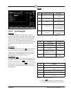
12.2 Logging On and
Access Levels
An E2 may be programmed with up to 25 different
users. A user basically consists of a username, a password,
and an access level. Whenever a username and password
are entered during login, the E2 searches the user records
for the username and password. If found, the E2 will log
the user in at the access level configured for the user in the
user records.
The access level determines how many of the E2’s fea-
tures the user may use. The E2 uses four access levels, one
bei
ng the lowest, and four being the highest. Table 12-1
gives a description of each level a
nd the capabilities they
have access to.
Table 12-1 - User Access
Levels
Level 1 Read-only access. Users may generally
only view status screens, setpoints, and
some system settings.
Level 2 Setpoint and bypass access. Users may
perform all the
tasks a level 1 user may,
and they may also change control setpoints
and bypass some devices.
Level 3 Configuration and override access. Users
m
ay perform all the tasks a level 2 user
may, and they may also override system
settings, create new cells, and program
new applications.
Level 4 System Administrator access. All E2 func-
tions are accessible by a level 4 user.


