


Sensors and Transducers Mounting • 3-9
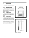
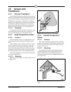
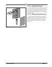
3.5.7 Product Temperature
Probes
The product temperature probe is designed to be used
alongside food products in a refrigeration case or freezer.
The product probe uses a thermistor type temperature sen-
sor in a sealed, cylindrical contai
ner (approximately 16
oz.). A magnet is contained at the bottom the probe’s
enclosure to allow easy attachment to a side or bottom of a
refrigeration case.
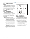
3.5.8 Humidity Sensors and
Humidistats
3.5.8.1 Indoor RH Sensor
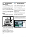
The indoor relative humidity sensor should be
mounted in a central location within the zone to be mea-
sured, away from doors, windows, vents, heaters, and out-
side walls that could affect te
mperature readings. The
sensor should be between four and six feet from the floor.
Note that this sensor generates a small amount of heat;
therefore, do not mount temperature sensors directly
above RH sensors.
Mount RH sensor (P/
N 203-5751) as follows:
1. With a flat-head screwdriver, push down the
middle
tab on the top of the sensor case and
pop the lid off to expose the circuit board.
2. Insert the flat-head screwdrive
r into the two
slots on either side of the top of the sensor
case and twist to separate the back plate from
the case.
3. Remove the knock-outs from the back plate
before m
ounting so wires may be threaded
through.
4. Mount the back plate to the wall using the
two
open mounting holes on the top and bot-
tom of the plate.
5. Replace the cover on top of the back plate by
lin
ing up the tabs, and snap the lid back into
place.
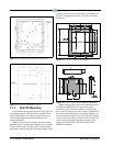
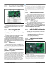
Figure 3-23
- Indoor RH Mounting Dimensions
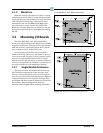
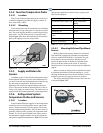
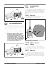
3.5.8.2 Outdoor RH Sensors
The outdoor RH sensor (P/N 203-5761)
The outdoor RH sensor (P/N 203-5761) should always
be mounted on the north side of the building if in the
Northern Hemisphere, or on the south side if in the South-
ern Hemisphere. The sensor should be mounted under an
ov
erhang or otherwise out of direct sunlight (if possible).
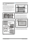
Mount the RH sensor (P/N 203
-5761) as follows:
1. Secure the rear side of
the enclosure to the out-
side wall using the two mounting brackets, as
show
n in Figure 3-24. The tub
e holding the sen-
sor element should point straight down.
2. If you will be running the sensor cable through
th
e wall behind the sensor, cut or drill a hole in
the wall through the hole in the enclosure.