


6-2 • E2 RX/BX/CX I&O Manual 026-1614 Rev 4 5-JAN-2013
6.1.2 MultiFlex-Plus (+) Board
The MultiFlex-plus board contains a replacement
RS485 transceiver chip that presents less of a load on the
network than a non-plus board. This increases the maxi-
mum number of devices that can be
placed on the network,
but not the number of board types an Einstein controller
can communicate with.
The MultiFlex-plus board now
accounts for only 1/8
the load of a non-plus board with 32 total devices on the
network (one Einstein controller + 31 boards). This new
conversion allows for the placement of 256 devices on the
network (one Einstein controller + 255 boards). The num-
ber of boards an Einstein controller can support is
increased
from 31 up to 255 using MultiFlex-plus boards
only. In other words, the number of I/O net devices are no
longer restricted by the I/O net 31-node limitation.
NOTE: The MultiFlex-plus board replaces the
old-style MultiFlex boards and is currently
being shi
pped.
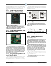
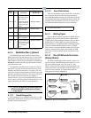
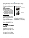
6.1.2.1 Board Designation
Plus boards are always identified with a plus (+) sign
that appears on the plastic insulating cover on the top of
the board, after the board name.
6.1.2.2 Board Calculations
With X as the number of plus boards and Y as the num-
ber of non-plus boards, use the following equation to
ensure th
at the number of devices on your network has not
exceeded the maximum load limitation of the network. For
example, if the total number of devices is less than 256,
the maximum load limitation has not been exceeded.
X + (Y • 8) < 256
6.1.3 Wiring Types
Emerson Retail Solutions specifies all RS485 I/O and
MODBUS wiring used by the E2 must be Belden 8641
(24AWG, 300V, Emerson Retail Solutions P/N 135-8641);
Belden 8761 (22 AWG, 300V not stocked by Emerson
Retail Solutions); or a 600V-shielded 22AWG equivalent
stocked by Emerson Retail Solutions (P/N 135-0600).
These are two-connector shielded twisted pair cables that
support a maximum daisy chain cable distance of 4000
feet (1219 m) between the E2 and the end device on the
network.
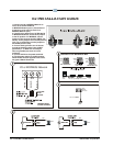
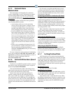
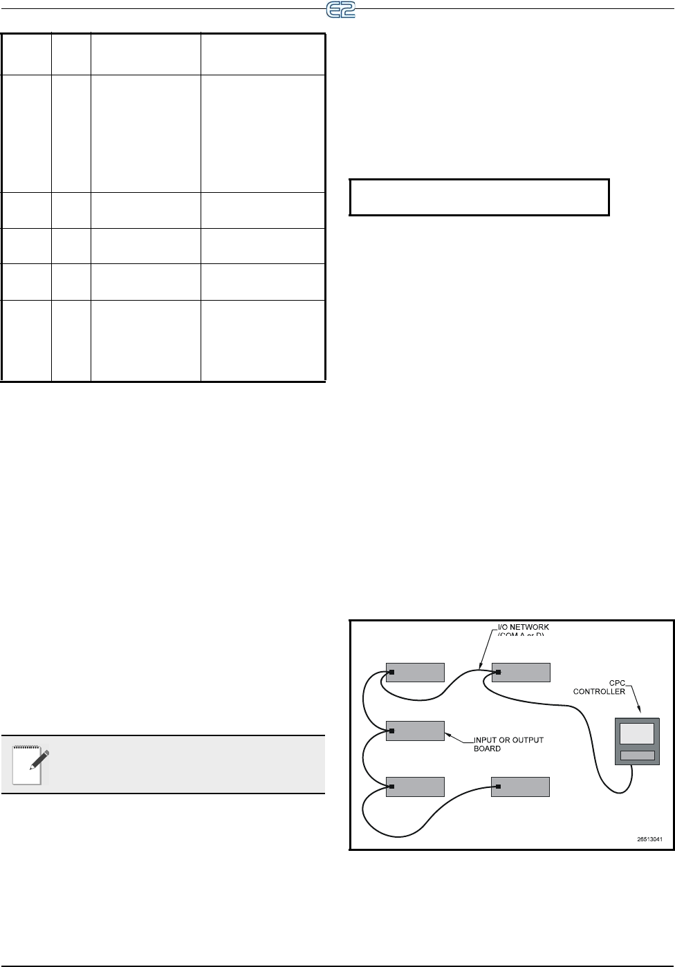
6.1.4 The I/O Network Structure
(Daisy Chains)
The RS485 Input/Output (I/O) Network connects all
input and output communication boards together in a sin-
gle open communications loop
. This loop, or “daisy
chain,” connects the E2 to multiple input and output com-
munication boards, and terminates
at the last input or out-
put board on the network. A diagram of this network
arrangem
ent is shown in Figure 6-1.
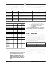
Figure 6-1
- I/O Network Configurations
RCB 32 MultiFlex RCB
advanced
rooftop
unit controller
MultiFlex RCB
RCB-P 32 MultiFlex RCB-P
(Pulse) advanced
roof
top unit con-
troller
MultiFlex RCB-P
PAK 32 MultiFlex PAK
ra
ck controller
MultiFlex PAK
CCB 99 CCB case control-
lers
CCBs
ESR 31 MultiFlex ESR
valve controller
MultiFlex ESR
CUB-
II
32 Single condensing
unit controller (one
compressor
and up
to 4 condenser
fans)
MultiFlex CUB II
Board
Ty
pe
Max # Translation
Boards That Match
Board Type
Table 6-1 - Board Types and Boards Included in Each Type