


The I/O Network The RS485 Network and Hardware Setup • 6-3
6.1.5 Network Noise
Minimization
Site environments will frequently have numerous
sources of high EMI, or “noise,” that must be accounted
for when routing RS485 network cable. Although the
cable is shielded against noise,
the installer must follow
best practices for minimizing network noise.
In general, installers should follow these guidelines
when installing RS485 networks:
• Avoid running cable next to noise-generating
devices, such as motor starters, contactors, invert
-
ers, fluorescent light ballasts, arc welders, etc. If
possible, keep cable less than 1 foot away from
noise-generating devices (ideally, at least 5 feet).
• Do not run RS485 cable in the same conduit as
high-voltage wiring, such as 120VAC or 240VAC
power wiring. Keep RS485 cable a minimum of 3
inches away from high-voltage wiring (ideally, at
least 12 inches). If RS485 must cross paths with
high-voltage wiring, cross them perpendicular —
running RS485 and high-voltage wire in parallel
increases the amount of noise induced on the net
-
work.
• Ensure you are grounding each input device’s 0V
power terminal to a separate earth ground, and set
-
ting the termination and biasing jumpers as
instructed in
Section 6.1.8, Setting the Terminating
and Biasing Jumpers.
For more instructions on best practices for minimizing
noise, refer to publication 026-1903, E2 Controller Wir
-
ing Practices, available in the Product Manuals section of
the Emerson Climate Technologies Web site:
www.emersonclimate.com
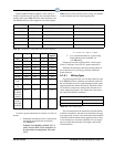
6.1.6 Network ID Numbers (Board
Numbers)
Each device on an RS485 segment has either a network
dip switch or rotary dials that must be used to assign the
board a unique network ID number.
The network ID number makes a board unique from
other boards on the network of the same type. This allows
E2 to find it and communicate with it easily.
Boards of the same type should be numbered in
sequence, starting with one and continuing with two,
three, and so forth. For example, if a segment contains
four 16AI boards and five 8RO boards, you should num
-
ber the 16AIs one, two, three, and four; and the 8ROs one,
two, three, four, and five. The same should be done with
multiple 4AO and 8DO boards, and IRLDS leak detection
units.
For all boards, except 8IO and 8DO boards, the net-
work dip switch labeled S1 (or S3 for the 16AI board) is
used to set the unique board number of the unit and the
baud rate. The 8IO and 8DO uses rotary dials to set the
board number of the unit.
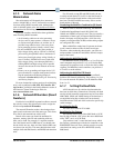
Numbering the MultiFlex Combination I/O Boards
When it comes to network numbering, the MultiFlex
Combination Input/Output boards (88, 88AO, 168,
168AO, and 168DO) are special cases. They are actually a
combination of three types
of Emerson Retail Solutions
boards: the inputs are configured like a 16AI, the relay
outputs are configured like an 8RO, and the analog outputs
are configured like a 4AO.
When a MultiFlex combo board is present on the net-
work, it must be addressed like all three board types.
Therefore, when numbering these boards, you must set a
unique number for both the 16AI, 8RO, and 4AO compo
-
nents of the board.
Addressing the MultiFlex Boards
For MultiFlex boards, set positions 1 to 5 on S3 for the
16AI component and positions 1 to 5 on S4 for the 8RO
component. Set positions 6 to 8 on S4 for the 4AO or 4DO
segment. For MultiFlex board controllers, use positions 1
to 5 on S3 to set the address.
Addressing the MultiFlex ESR Boards
The MultiFlex ESR uses standard Emerson Retail
Solutions I/O Network addressing. Set positions 1 to 5 on
S1 to set the network ID (address) of the MultiFlex ESR
from 1 to 31.
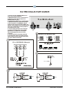
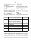
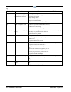
6.1.7 Setting the Baud Rate
All I/O boards have dip switches that determine the
baud rate at which they communicate. Currently, the baud
rate dip switch in network components may be set at either
4800, 9600, 19200, and 38400. Setting of the baud rate is
accomplished using dip switches (refer to the board’s
installation sheets at the end of this section for specific dip
switch settings).
Baud Rate for the E2
The baud rate default for E2 is 9600.
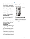
Baud Rate for the Gateway
The Gateway can be set to either 9600 baud or 19.2K
baud by dip switch #6. “ON” places the rate at 9600 baud
while “OFF” sets it at 19.2K baud.
Dip switches 6 and 7 control the baud rate at which
the Gateway communicates with the site controller on the
RS485RS485 Network. These switches must be set to the
same baud rate setting as the E2 or REFLECS (usually
9600 baud).