


Sensor Control Software Overview • 11-39
loads.
11.11.6.1 Power Monitoring Input
The Input Type Selection parameter defines the way
the Power Monitoring input (INPUT under the Inputs tab
in application Setup) will be used. The parameter can be
set to: KW Analog, or Pulse KWH.
Settings
When KW Analog is selected, verify the input is con-
nected to a board and point that
is set up with Engineering
Units of KW. When Pulse KWH has been selected, verify
the input is connected to a board and point that is set up
with Engineering Units of KW.
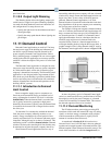
11.12 Sensor Control
11.12.1 Overview
The E2 is equipped with numerous generic control
modules that may be used both for simple monitoring of
an analog or digital sensor and for simple Cut In/Cut Out
control of a digital output. These modules are called Sen-
sor Control modules.
There are two different Sensor Control Module types.
Analog
Sensor Control modules read the values from
one or more analog sensors, compare them to a set of Cut
In/Cut Out setpoints, and operate a digital output (such as
a relay) based on the analog input in relation to the set-
points.
Digital Sensor Control modules
read the values from
one or more digital sensors, combine them using a series
of logical commands, and operate a digital output (such as
a relay) based on the result of the logical combination.
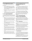
11.12.2 Analog Sensor Control
On a basic level, an Analog Sensor Control module
performs three functions:
• COMBINER: Up to four analog inputs are com-
bined into a single analog value.
• CUT IN/CUT OUT CONTROL: The combined
inp
ut value is compared to a Cut In/Cut Out set-
point. Based on this comparison, a digital output
will be turned ON or
OFF.
• ALARMING: Alarms and notices can be generated
based on th
e combined value of the inputs and its
relation to a set of high and low alarm and notice
setpoints.
11.12.3 Cut In/Cut Out Setpoint Con-
trol
Cut In/Cut Out setpoints work differently depending
upon whether the Cut In/Cut Out setpoint is higher.
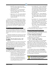
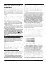
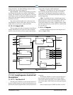
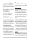
Cut In Higher Than Cut Out
Figure 11-22
- Cut In Setpoint Higher than Cut Out
When the Cut In setpoint is higher than the Cut Out
setpoint, the Sensor Control output turns ON when the
sensor input goes higher than the Cut In setpoint. The Sen-
sor Control output remains ON until the input falls below
th
e Cut Out setpoint, at which time the output turns OFF.
(See Figure 11-22 for an illustration).
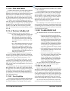
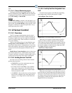
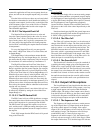
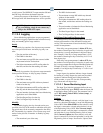
Cut/In Lower Than Cut/Out
Figure 11-23
- Cut/In Setpoint Lower Than Cut/Out
When the Cut In setpoint is lower than the Cut Out set-
point, the Sensor Control output turns ON when the sensor
in
put goes lower than the Cut In setpoint. The Sensor Con-
trol output remains ON until the input rises above the Cut
Ou
t setpoint, at which time the output turns OFF. (See
Figure 11-23 for an illustration).