2-8 • E2 RX/BX/CX I&O Manual 026-1614 Rev 4 5-JAN-2013
RJ-11 to male RJ-11 cable.
NOTE: The 9V battery and 9-12V DC adapter
connection are not used on this HHT model
(P/N
814-3110).
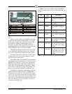
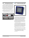
Figure 2-12
- Hand-held Terminal (814-3110)
LEGEND
Up Arrow - moves to previous screen,
editable field, or top of screen
1
3
4
11
7
8
9
10
2
The power switch determines if the HHT is
in self-powered mode (BATT), ext power (EXT),
or if powered from a target device (HOST)
1
4
3
2
RS-485 Connector
Enter - save into memory
5
6
7
8
10
9
11
12
13
14
LCD - four lines of 16 characters
Numeric keypad
F1 - Home Screen
External Power Connector (9-12 VDC)
Scrolls list selections and scrolls through
ASCII characters if in a text field
5
613
F2- Main Menu
Right Arrow - selects last editable field
starting from bottom of screen; selects
last editable field from bottom to top
Down Arrow - moves to next screen,
editable field, end of screen, or advances
Cancel - clears/erases text in editable field;
cancels overrides
12
14
Left Arrow - selects first editable field from
top of screen, and next editable field from
top to bottom
2.2.5 The 8RO and 8ROSMT Relay
Boards
The 8RO (P/N 810-3005) board is a general-purpose
board used to connect an E2 to any of eight standard con-
trol relay outputs, but is now obsolete and has been
replaced by the 8ROSMT (P/N
810-3006) board.
To function, the 8RO board must be connected through
eith
er the Echelon Network or the RS485 I/O Network to
the E2. When properly installed, the 8RO receives an elec-
trical impulse from the E2, which eith
er opens or closes
any of eight contact relays. Output definitions within the
E2 allow the user to configure the 8RO board to interact
with any refrigeration system or environmental control
component.
The 8RO board is the direct link between the E2 and
com
ponent operation. Information gathered by the con-
troller from the input boards is
checked against current
stored setpoints. If differences in the received input data
and the setpoint information are detected, a signal is either
sent to the proper 8RO relay, or an existing signal is dis-
continued. Through the use of this relay signal, control
fu
nctions that can be properly maintained by a simple con-
tact closure sequence are effectively
operated by the E2.
The 8RO board is easily installed and operated within
th
e Emerson Retail Solutions Network environment
because of its straightforward design. Several of these fea-
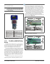
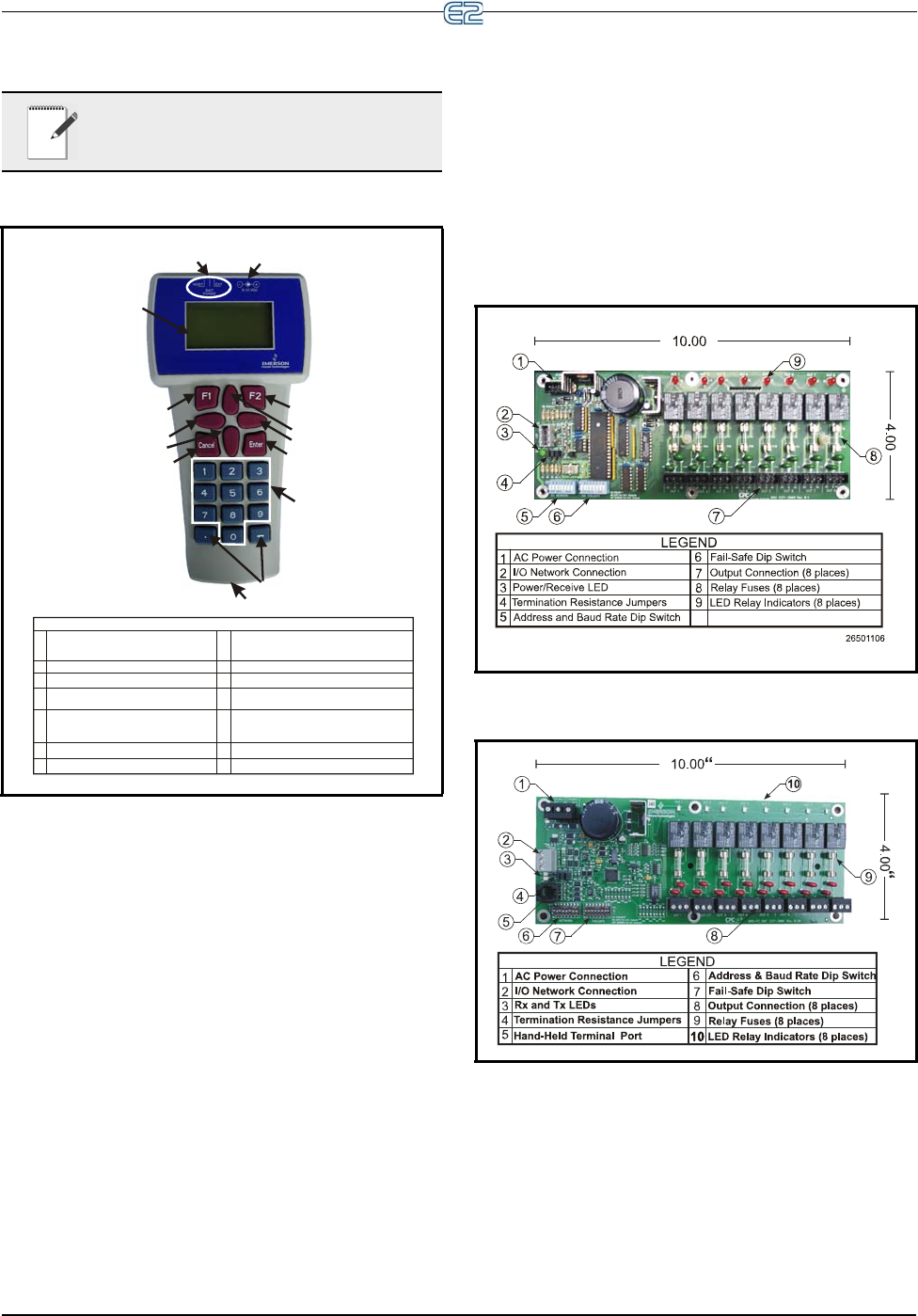
tures are shown in Figure 2-13.
Figure 2-13 - 8RO Relay Output Board
Figure 2-14 - 8ROSMT Relay Output Board


