4-2 • E2 RX/BX/CX I&O Manual 026-1614 Rev 4 5-JAN-2013
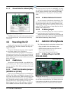
4.1.3 Power Interface Board (PIB)
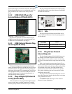
Figure 4-3 - Power Interface Board
The PIB interfaces the power and most all communica-
tions with the main board, and contains all
field wiring
connections.
4.2 Powering the E2
Starting at the lower right side of the PIB, the first plug
is the 24VAC input. This must terminate into the power
supply transformer.
E2 requires 24VAC Class 2 power, which is supplied
by a non-center
-tapped Class 2 transformer.
Emerson Retail Solutions sup
plies two transformers
that may be used to power E2s: one for use with 110VAC
(P/N 640-0041), and one for use with 220VAC (P/N 640-
0042). Both transformers are rated at 50VA, and each will
power one E2 unit.
4.2.1 RS485 Ports
On the lower left side of the PIB are two RS485 Net-
work connector ports. This is where
all I/O boards (except
the case controllers, TD3, ESR8, and Echelon I/O boards)
are connected.
4.2.2 RS485 Termination Jumpers
(MODBUS or I/O Net)
There is one set of RS485 jumpers for each RS485 port
(COM2A-2B; COM6; and COM4A-B). Jumpers J8-J10
are located directly above the COM2A connector port, and
jumpers J11-J13 are located directly above the COM2B
port. The RS485 termination jumpers (J8-J22) are used to
terminate the devices at the beginning and end of an
RS485 Network. If the E2 is the beginning of all RS485
I/O or MODBUS Networks, all three of these jumpers
shou
ld be set to the UP position. For MODBUS, the jump-
ers should all be in the top-most position (MO
D). For I/O
Net, the jumpers should be in the middle position (I/O).
For no termination, set the jumpers to the down position
(NO).
4.2.3 Echelon Network Connect
The next connector is the Echelon Network plug. The
one connector handles both input and output connections.
The input and output cables are connected directly to the
Echelon plug. This plug is the connection to the Case Con-
troller (CC-100), the Evaporator S
tepper Regulator board
(ESR8), TD3s, and other E2s.
4.2.4 Echelon Jumper
There is one Echelon jumper (J2) located on the Eche-
lon board that plugs into the main processor board.
Additional information about Echelon Networking and
termi
nating the network can be found in Section 8.3, Ech-
elon Network Structuring (Daisy-Chains).
4.3 Add-On E2 Peripherals
The E2 has many plug-in card options to choose from:
• Plug-in Echelon card with mounting screw
• RS485 Modem/communication expansion card
• Plug-in digital I/O Network card
• Plug-in Four-Channel Internal Repeater
4.3.1 Echelon Plug-In Card Kit
(P/N 638-4860)
Figure 4-4 - Echelon Card
Echelon is a two-conductor network that interconnects
E2s and other associated devices. All Echelon devices are
wired together using the daisy-chain method of network
structuring. For the E2 to communicate on the Echelon


