


Case Control Circuits Software Overview • 11-13
defined Pump Down and Run-Off times will be observed
as normal.
Electric Defrost
Electric defrost uses electric heaters to defrost the
evaporator coil. During electric defrost, the application
will turn the Defrost output ON, which will likewise acti
-
vate the heaters connected to the power module’s defrost
relay.
Any user-defined Pump Down and Run-Off times will
be observed as normal.
11.4.4.3 Defrost Termination
Both the start time and the end time of a defrost cycle
are determined by the user. The Pump Down, Defrost, and
Run-Off stages all have fixed durations, and when the last
stage of the cycle is complete, defrost is terminated.
However, a case controller may be programmed to ter-
minate the Defrost stage of the defrost cycle early if the
temperature inside the case rises above a fail-safe tempera
-
ture setpoint. For certain defrost types, defrost heat may
also be “pulsed” in order to keep the temperature below
the setpoint without terminating defrost.
Temperature Termination
One or more temperature sensors in the case circuit
may be designated as termination temperature sensors.
The values of these sensors are combined into a single
control value, and this value is compared to the setpoint. If
the termination control value is greater than the user-
defined setpoint, defrost will end, and the defrost cycle
will begin the Run-Off period (if applicable).
Termination sensors may be either analog temperature
sensors or digital closures (Klixons). Also, Case Circuit
applications may use the value of the analog case tempera
-
ture sensors for use in temperature termination.
Pulsed Defrost
Pulsed Defrost is only available if the circuit is using
Electric or Hot Gas defrost.
Pulsed Defrost is similar to Temperature Termination,
except when the termination temperature rises above the
setpoint, defrost does not terminate. Instead, the output
that applies defrost heat is turned OFF. The output will
remain OFF until the temperature falls below the setpoint,
at which time the output will come back ON.
The Case Circuit application will continue to pulse
defrost in this manner until the defrost time has passed.
The defrost cycle will then begin the Run-Off period.
11.4.4.4 Demand Defrost
If a case is configured with a demand defrost sensor, a
case controller may use their inputs as a means of keeping
scheduled defrost cycles from occurring when frost levels
are not high enough to require a defrost.
The optical demand defrost sensor may be either an
analog or digital type sensor. When this sensor detects no
major build-up of frost, the Case Circuit application
ignores all scheduled calls for defrost and continues in
refrigeration mode. When the sensor detects frost, the
defrost inhibit is cancelled, and the case circuit will enter
defrost at the next scheduled time.
A demand defrost inhibit only keeps scheduled
defrosts from occurring. Any manual calls for a defrost
cycle will occur as normal. CCB demand defrost is cur
-
rently not supported in E2. Demand sensors, if present on
the circuit, will be ignored.
Demand Fail-Safe Time
To protect against demand defrost sensors that may not
be working properly, a demand fail-safe time may be set
up. Demand fail-safe times limit the amount of time a
defrost inhibit may last. If a demand defrost sensor does
not detect frost for an amount of time equal to the Demand
Fail-Safe Time, the defrost inhibit is lifted and the circuit
will enter defrost at the next scheduled time.
11.4.4.5 Emergency Defrost
When necessary, a user can initiate an emergency
defrost cycle from a circuit. Emergency defrost cycles are
similar to normal defrost cycles, except an emergency
defrost cycle will ignore all calls for termination and
remain in defrost for the entire programmed defrost time.
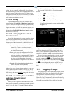
Emergency defrosts are initiated by the user from the
Case Control Circuit Bypass screen (see
Section 12.6,
Manual Defrost and Clean Mode).
11.4.4.6 The WAIT State
When a Case Control Circuit application enters defrost
mode, it sends a message out to all case controllers in the
circuit to begin defrost at the same time. However, since
each case in a circuit will have its own termination sen
-
sors, it is possible for some cases to terminate defrost
while defrosts in other cases continue.
When a case controller terminates defrost, it enters a
state of operation called “the WAIT state.” While in the
WAIT state, all refrigeration and defrost heat will remain
OFF. When the Case Control Circuit application detects
that all case controllers have entered the WAIT state, the
application will consider the defrost cycle completed, and
refrigeration will restart.
11.4.5 Anti-Sweat Control
A case controller manages its anti-sweat heaters by
monitoring the dewpoint in and around the case area. The
dewpoint input value is compared to the anti-sweat appli
-
cation’s control setpoints (the Full ON setpoint and the