


D-2 • E2 RX/BX/CX I&O Manual 026-1614 Rev 4 5-JAN-2013
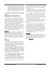
Throttling Range on page D-1.
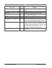
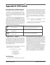
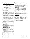
Figure D-1
- Throttling Range
.
26512028
CONTROL INPUT
OUTPUT AT
SETPOINT
(shown here as 50%)
0% 100%
THROTTLING
RANGE
Example 1: Suppose a Case Control application has a
throttling range of 10 degrees. Also, for simplicity’s sake,
assume only the Proportional Mode is active and the pro-
portional constant Kp is one. The system begins with a 0%
out
put at the bottom of the Throttling Range and with an
input value of 24F. Because the throttling range is 10
degrees, Proportional Mode will gradually add 100% to
the output percentage as the input changes to 34 over
time.
Suppose, for example, the input increases by one
degr
ee every time an update occurs. The following adjust-
ment would then likewise occur after every update:
“P” mode adj. = (1.0)(1 degree) / 10 degrees = 0.1 = 10%
After 10 updates, the input value would be 34F and
the output would be 100%. The same would happen if it
were five updates at two degrees each or one hundred
updates at 0.1 degrees each. In every case, the tempera-
ture travels a total of 10 degrees, and because the throt-
tling range is also 10 degrees, the output travels from 0%
to 10
0% proportionally.
Higher Throttling Range values will result in a wider
0-100% range, and
therefore will result in smaller reaction
to changes in input values.
Proportional Constant (K
p
)
The Proportional Constant is simply a multiplier that
can be used to fine-tune the size of the Proportional Mode
adjustment. Raising the value of K
p
results in a greater
reaction to input value changes, while lowering it results
in a smaller reaction.
Changing K
p
is essentially the same thing as changing
the value of the throttling range. For example, having a TR
of 10 and a K
p
of 2 is the same as having a TR of 5 and a
K
p
of 1. Mathematically speaking, the effective propor-
tional range is calculated by dividing the Throttling Range
by K
p.
If Proportional Mode is functioning incorrectly in your
system, it may be more appropriate for you to change the
Throttling Range value to a more appropriate value. K
p
is
designed as a fine-tuning constant (for example, it might
be used to speed up reaction slightly by setting it to 1.04,
or to slow down reaction by setting it to 0.98).
Integral Mode
The Integral Mode (also called “I” Mode) is the por-
tion of PID control that seeks to make the input equal to
the setpoint.
When an update occurs, the Integral Mode
measures the difference between the current input value
and the setpoint. The size of this difference determines
Integral Mode’s output percentage adjustment.
Why “I” Mode is Necessary
Though Proportional Mode handles the majority of the
workload during PID control, there are two major short-
comings that make the “I” Mode necessary.
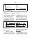
Proportional Offset
Proportional Mode, if left to operate all by itself, is
only capable of stopping the error from changing. When
the error is not changing, neither is the “P” portion of the
output. This means the system may reach stability at any
value, regardless of whether it is above or below the set-
point (see Figure D-2). Proportional Mode alone has no
mechanism that can bring the error to zero
after stability
has occurred. The “I” Mode is necessary in order to move
the input in the direction of the setpoint.