


2-2 • E2 RX/BX/CX I&O Manual 026-1614 Rev 4 5-JAN-2013
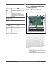
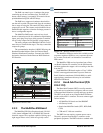
2.1.1 E2 Main Processor Board
(CPU)
Figure 2-2 - E2 CPU
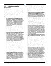
The E2 CPU or main processor board (Figure 2-2)
contains the CPU, Ethernet port, and memory used for log-
ging. The coin battery for the E2
is located on this board
and protects log and alarm data during power loss. The
main processor board connects to the PIB via a ribbon
cable. The RX- and CX-100 versions support mono-
chrome display only. For optimum viewing, backlight and
contrast
adjusts are available for customizing the mono-
chrome display depending on the user’s needs.
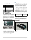
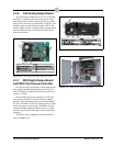
2.1.2 E2 Processor Interface Board
(PIB)
Figure 2-3 - E2 PIB
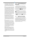
The E2 Processor Interface Board (PIB) interfaces the
power and most all communications with the main proces-
sor board, and contains all field wiring connections. The
PIB allows you to connect an external
keyboard, accessory
cards, and an external computer. All RS485 connectors are
located on the PIB.
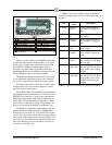
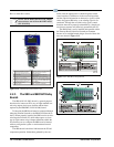
2.1.3 E2 Keypad
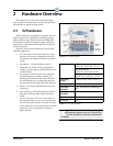
Figure 2-4 - E2 Keyboard
The E2 has a QWERTY style keyboard layout with
two rows of function keys. The first row (-) is
comprised of screen-specific function keys, and the sec-
ond row has designated icon keys. The five icon keys are
Help , Alarms , Ho
me , Menu , and
Back .
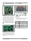
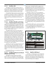
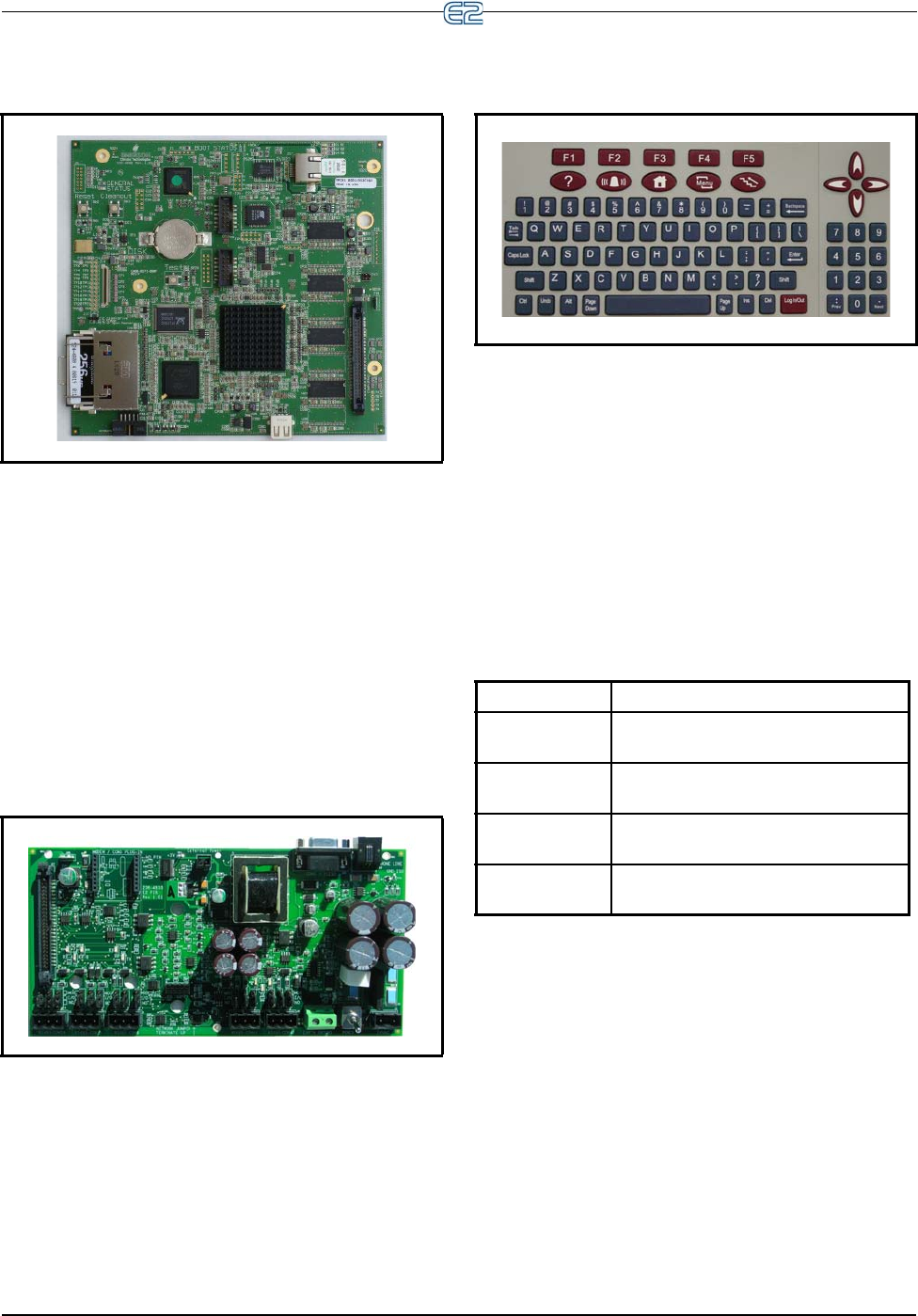
2.1.4 LEDs
The PIB, main processor board, and keyboard (located
behind the main board) LEDs can be used to determine the
status of normal operating parameters for the unit.
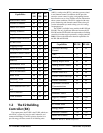
Table 2-2 -
PIB LED’s Status
PIB LEDs Status
Green (14) ON: Power is being applied to the
PI
B
Yellow (RX1) ON: Communication is being re-
ceived on RS485 Port 1A
Yellow (RX2) ON: Communication is being re-
ceived on RS485 Port 1B
Red (TX) ON: Communication is being sent on
RS485
Port 1A and 1B