


Loop/Sequence Control Software Overview • 11-41
change drastically. The filtered PID percentage is sent to
the final control cell, the Override cell.
Step 5: Override - Once the PID percentage is figured,
the Override cell provides for overrides of the PID per-
centage. The Override cell, when activated by
a user-initi-
ated manual override, will block the PID percentage from
bein
g sent to the outputs, replacing it with a fixed value
specified by the user.
The value from the Override cells is then sent to the
Loop/
Sequence Control’s PID output, and also to the two
output cells for conversion to stages and PWM.
11.13.1.2 Output Cells
The two output cells make no alteration of the PID per-
centage determined by the cont
rol cells, but re-interpret
them in a way that can be used for systems with multiple
stages and/or with pulse width modulation.
Sequencer - The
Sequencer cell will use the percent-
age to activate an equivalent percentage of its defined
stage ou
tputs. The Sequencer supports up to eight cells,
and also provides for minimum on/off times and first-on/
last-off sequencing.
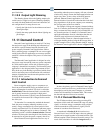
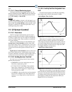
PWM - Th
e PWM cell drives a digital output whose
ON time per pulse width modulation period is equal to the
PID percentage. In other words, if the PWM cell is set
with a pulse width of 10 seconds, a PID percentage of 60%
turns the output ON for 6 seconds, OFF for 4 seconds, ON
for 6 seconds, etc.
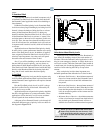
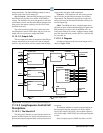
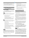
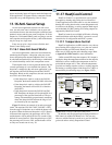
11.13.1.3 Diagram
An abstract diagram of the control and output cells is
shown in Figure 11-24.
Figure 11-24
- Loop/Sequence Control Application Diagram
SELECT CELL
SETPT FLOAT
PID CONTROL
FILTER
OVERRIDE
SEQUENCER
PWM
Occ SP
Unoc SP
Occupied
In 1
In 2
Occup
SP In
Float
SP Out
Setpoint
Input PID Out
In Out
In Out
Input
In Out
Stage 1
Stage 2
Stage 3
Stage 4
Stage 5
Stage 6
Stage 7
Stage 8
DVAV
DV = Digital Value
AV = Analog Value
AV
AV
DV
AV
AV
AV
AV AV
AV
AV
AV AV
AV
DV
DV
DV
DV
DV
DV
DV
DV
DV
Float
Control Value
Analog PID/PWM
Loop Output
Digital Stage
1-8 Output
Digital PWM
Output
11.13.2 Loop/Sequence Control Cell
Descriptions
11.13.2.1 The Select Cell
The Select cell’s function is to provide the control set-
point to the PID Control cell, and to switch between occu-
pied and unoccupied setpoints bas
ed on the current state of
occupancy.
To determine whether to use th
e occupied setpoint or
the unoccupied setpoint, the Select cell reads a digital
input. If this input is ON (OCC), the occupied setpoint is
used. If this input is OFF (UNO), the unoccupied setpoint
is used.
If the occupancy input is NONE, the Select cell will