


Agilent E1441A Function Generator Tutorial 155
Appendix C
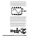
The maximum output frequency, with the condition that every waveshape point in
RAM is output every waveform cycle, is defined by:
F
out = Fclk / Points
The minimum number of points required to accurately reproduce a waveshape will
determine the maximum useful output frequency using the same equation.
The rule governing waveforms is referred to as the
Nyquist Sampling Theorem, which
states that you must include at least two points from the highest frequency component
of the signal you are attempting to reproduce.
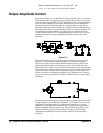
Signal Imperfections
Most signal imperfections are easiest to observe in the frequency domain using a
spectrum analyzer. Sampling theory predicts the location and size of spurious signals
resulting from the sampling processes used by
DDS generators. In fact, since DDS
generators use a fixed sampling rate (40 MHz for the Agilent E1441A), spurious
signals can be removed with a fixed frequency “anti-alias” filter. A 17 MHz,
ninth-order elliptical filter providing a sharp cut-off (in excess of 60 dB attenuation
for signals greater than 19 MHz) is used for sine wave outputs. A 10 MHz,
seventh-order Bessel filter is used for non-sine wave outputs. The Bessel filter
provides slower amplitude roll-off for anti-alias filtering, but maintains linear phase
response to minimize shape distortion for complex waveshapes. The Agilent
E1441A automatically selects the appropriate filter when the output function is
selected.
All digital-to-analog converters, including those used in
DDS generators, produce
spurious signals resulting from non-ideal performance. These spurious signals are
harmonically related to the desired output signal. At lower frequencies, the Agilent
E1441A's 12-bit waveform
DAC produces spurious signals near the -74 dBc level
(decibels below the carrier or output signal) as described by the equation on the
following page. The Agilent E1441A uses the complete vertical resolution (N=1) of
the
DAC for all internal waveshapes, thus minimizing amplitude quantization error.
At higher output frequencies, additional
DAC errors produce non-harmonic spurious
outputs. These are signals “folded back” or aliased to a frequency within the signal
bandwidth. A “perfect”
DAC will also produce a wideband noise floor due to
amplitude quantization. The noise floor for a 12-bit
DAC will be near the -74 dBc
level; this corresponds to a noise density of -148 dBc/Hz for sine wave outputs from
the Agilent E1441A.
Amplitude Quantization ≤ – (20 x log
10
( N x 4096 ) + 1.8 ) dBc
where “N” is the fraction of available DAC codes used to describe
the signal waveshape (0 ≤ N ≤ 1).
Another type of waveform error visible in the frequency domain is phase truncation
error. This error results from time quantization of the output waveform. Whenever
a waveshape is described by a finite number of horizontal points (length), it has been
sampled in time (or quantized) causing a phase truncation error. Spurious signals
caused by phase truncation introduce jitter into the output waveform. This may be
regarded as time (and phase) displacement of output zero crossings.
Phase truncation causes phase modulation of the output signal which results in
spurious harmonics (see the equation below). For lower output frequencies, the
phase accumulator periodically does not advance
RAM addresses, causing the DAC
to deliver the same voltage as recorded on the previous clock cycle. Therefore, the
phase “slips” back by 360°/ points before continuing to move forward again. When
RAM address increments are the same on each cycle of the output, phase truncation
error (and jitter) are essentially zero. All standard waveshapes in the Agilent E1441A
are generated with at least 16,000 waveform points which results in spurious signals
below the wide-band noise floor of the
DAC.