


Agilent E1441A Function Generator Tutorial 159
Appendix C
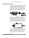
In amplitude modulation, the amplitude of the carrier varies between zero and twice
its normal value for 100% modulation. The percent modulation depth is the ratio of
the peak information signal amplitude to the constant.
When amplitude modulation
is selected, the Agilent E1441A automatically reduces its peak-to-peak amplitude by
one-half so that a 100% modulation depth signal can be output
. Amplitude settings
are defined to set the 100% peak-to-peak amplitude independent of the modulation
depth setting. Vrms and dBm amplitude settings are not accurate in AM since signals
are very complex.
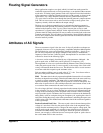
Frequency Modulation (FM) Frequency Modulation is a process of producing a
wave whose frequency varies as a function of the instantaneous amplitude of the
modulating information signal. The extent of carrier frequency change is called
deviation. The frequency deviations are caused by the amplitude changes of the
modulating information signal. You can set the amount of the peak frequency in
FM
with the deviation parameter.
In frequency modulation, “100% modulation” has a different meaning than in
AM.
Modulation of 100% in
FM indicates a variation of the carrier by the amount of the
full permissible deviation. Since the modulating signal only varies frequency, the
amplitude of the signal remains constant regardless of the modulation. The function
generator uses the deviation parameter to describe the peak frequency change above
or below the carrier in response to a corresponding amplitude peak of the modulating
signal. For
FM signals, the bandwidth of the modulated signal can be approximated
by:
BW ≈ 2 x (Deviation + Information Signal Bandwidth) For wideband FM
BW ≈ 2 x (Information Signal Bandwidth)
For narrowband FM
Narrowband FM occurs when the ratio of the deviation frequency to the information
signal bandwidth is approximately 0.01 or less. Wideband commercial
FM radio
stations in the United States use a 75 kHz peak deviation (150 kHz peak-to-peak)
and audio signals band-limited to 15 kHz to achieve 200 kHz channel-to-channel
spacing from the 180 kHz bandwidth.
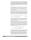
Frequency Sweep The Agilent E1441A performs phase-continuous frequency
sweeping — stepping from the sweep start frequency to the sweep stop frequency
with between 2,048 and 4,096 discrete frequency steps. The direction of frequency
sweeps can be varied by setting the stop frequency either above or below the start
frequency. Individual frequency steps are either linearly or logarithmically spaced
based on the sweep mode setting. Like
FSK modulation (described on the next page),
the sweep function is also a special case of frequency modulation (
FM). All of the
FM operations described on the previous page also apply to sweep when the
following translations are applied:
The modulation waveshape for sweeps is a ramp wave or exponential wave for linear
or log sweeps, respectively. The logic sense of the ramp or exponential modulation
signal (positive or negative ramp) is selected when the stop frequency is either larger
or smaller than the start frequency. Like the
FM function, changes to sweep
parameters cause the generator to automatically compute a modulation signal and
download it into modulation
RAM. Similarly, the sweep time parameter adjusts the
period of the modulating waveform. The sweep function also allows triggered
operation. This is like frequency modulating with a single cycle burst of the
modulating signal beginning when a trigger is received. Trigger signals can come
C
arrier Frequency
Start Frequency Stop Frequency+
2
--------- ------------------------------ ------------ ------------------------------ --------
---
=
D
eviation
Start Frequency Stop Frequency–
2
--------- ----------------------------- ------------- ------------------------------
----
=