


Agilent E1441A Function Generator Tutorial 157
Appendix C
Floating Signal Generators
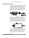
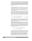
Many applications require a test signal which is isolated from earth ground for
connection to powered circuits, to avoid ground loops, or to minimize other common
mode noise. A floating signal generator such as the Agilent E1441A has both sides
of the output
BNC connector isolated from chassis (earth) ground. As shown in the
figure below, any voltage difference between the two ground reference points
(V
ground) causes a current to flow through the function generator's output common
lead. This can cause errors such as noise and offset voltage (usually power- line
frequency related), which are added to the output voltage.
The best way to eliminate ground loops is to maintain the function generator's
isolation from earth ground. The function generator's isolation impedance will be
reduced as the frequency of the V
ground source increases due to low-to-earth
capacitance C
le (approximately 4000 pF for the Agilent E1441A). If the function
generator must be earth-referenced, be sure to connect it (and the load) to the same
common ground point. This will reduce or eliminate the voltage difference between
devices. Also, make sure the function generator and load are connected to the same
electrical outlet if possible.
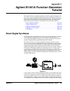
Attributes of AC Signals
The most common ac signal is the sine wave. In fact, all periodic waveshapes are
composed of sine waves of varying frequency, amplitude, and phase added together.
The individual sine waves are harmonically related to each other — that is to say,
the sine wave frequencies are integer multiples of the lowest (or fundamental)
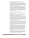
frequency of the waveform. Unlike dc signals, the amplitude of ac waveforms varies
with time as shown in the following figure.
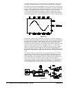
A sine wave can be uniquely described by any of the parameters indicated -- the
peak-to-peak value, or RMS value, and its period (T) or frequency (1/T).
The magnitude of a sine wave can be described by the
RMS value (effective heating
value), the peak-to-peak value (2 x zero-to-peak), or the average value. Each value
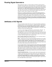
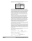
conveys information about the sine wave. The table below shows several common
waveforms with their respective peak and
RMS values.
Each waveshape exhibits a zero-to-peak value of "V" volts. Crest factor refers to
the ratio of the peak-to-RMS value of the waveform.
RMS The
RMS value is the only measured amplitude characteristic of a waveform
that does not depend on waveshape. Therefore, the
RMS value is the most useful way
to specify ac signal amplitudes. The
RMS value (or equivalent heating value)
specifies the ability of the ac signal to deliver power to a resistive load (heat). The
RMS value is equal to the dc value which produces the same amount of heat as the
ac waveform when connected to the same resistive load.
For a dc voltage, this heat is directly proportional to the amount of power dissipated
in the resistance. For an ac voltage, the heat in a resistive load is proportional to the
average of the instantaneous power dissipated in the resistance. This has meaning
only for periodic signals. The
RMS value of a periodic waveform can be obtained by
taking the dc values at each point along one complete cycle, squaring the values at
each point, finding the average value of the squared terms, and taking the square-root
of the average value. This method leads to the
RMS value of the waveform regardless
of the signal shape.
Peak-to-Peak and Peak Value The zero-to-peak value is the maximum positive
voltage of a waveform. Likewise, the peak-to-peak value is the magnitude of the
voltage from the maximum positive voltage to the most negative voltage peak. The
peak or peak-to-peak amplitude of a complex ac waveform does not necessarily
correlate to the
RMS heating value of the signal. When the specific waveform is
known, you can apply a correction factor to convert peak or peak-to- peak values to
the correct
RMS value for the waveform.