


Agilent E1441A Application Information 27
Chapter 2
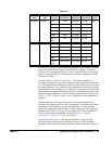
sync signal, you can disable the Sync terminal.
By default, the sync signal is routed to the Sync terminal (enabled).
When the sync signal is disabled, the output level on the Sync terminal is
indeterminate (it might be a
TTL “high” or a TTL “low”).
For sine, square, triangle, and ramp waveforms, the sync signal is a
TTL
“high” when the waveform's output is positive, relative to zero volts (or the
dc offset value). The signal is a
TTL “low” when the output is negative,
relative to zero volts (or the dc offset value).
For arbitrary waveforms, a momentary
TTL “high” pulse (> 200 ns) is output
which corresponds to the first downloaded point in the waveform.
For AM and FM, the sync signal is referenced to the modulating signal (not
the carrier). A momentary
TTL “high” pulse (> 200 ns) is output at each
zero-crossing point of the modulating signal.
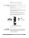
For the counted burst mode, a
TTL “low” signal is output while the specified
number of cycles is output (for the duration of the burst). After the specified
number of cycles has been output, the sync signal goes “high” until the next
burst.
For the external gated burst mode, the sync signal is a
TTL “high” when the
output is positive, relative to zero volts (or the dc offset value). The signal is
a
TTL “low” when the output is negative, relative to zero volts (or the dc
offset value).
For FSK, a momentary
TTL “high” pulse (> 200 ns) is output on the
transition to the “hop” frequency.
For frequency sweeps, the sync signal is a
TTL “low” at the start of the sweep
(when the start frequency is output) and is a
TTL “high” at the end of the
sweep (when the stop frequency is output).
Use the following command to set the SYNC signal mode:
OUTPut:SYNC OFF|ON
Setting is stored in volatile
memory.
Instrument State Storage You can store up to four different instrument states in non-volatile memory.
This enables you to recall the entire instrument configuration using the
*RCL common command.
Four memory locations (numbered 0, 1, 2, and 3) are available to store
instrument configurations. The state storage feature “remembers” the
function (including arbitrary waveforms), frequency, amplitude, dc offset,
duty cycle, as well as any modulation parameters. To recall a stored state,
you must use the same memory location used previously to store the state.
The instrument state in memory location 0 can become the "*RST" or
power-up state by setting MEMory:STATe:RECall:AUTO ON. See
reference for this command on page 85
You cannot recall the instrument state from a memory location that was not