


Service Procedures 171
Appendix D
Amplitude Flatness Verification
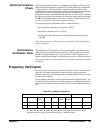
This test verifies the output amplitude flatness specification at selected
frequencies. If you use a Temperature Voltage Converter (TVC) (the
recommended method)
or a wide band ACrms voltmeter (with a 50 Ω feed through load), perform
this procedure as described. If you are using a measurement device that
requires a transfer measurement (for example, a power meter), make the
transfer in the reference measurement at 100 kHz.
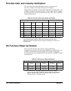
Set the function generator to the first output indicated in the table below and
make a reference measurement. Set each function generator output shown in
the table below. Measure the output of the function generator. Compare the
amplitude level measured to the reference measurement +/- the error shown
in the table. This test is a 50 Ω output termination test.
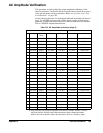
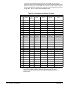
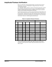
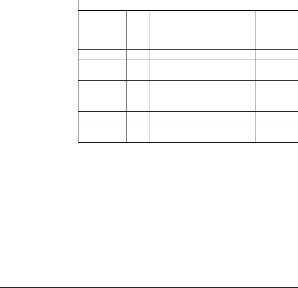
Table D-7. Amplitude Flatness Verification
Agilent E1441A Measurement
Function Out
Te r m
a
Ampl Freq Nominal Error
Q Sine wave 50 Ω 3.0 Vrms 1.00 kHz <reference>
Sine wave 50 Ω 3.0 Vrms 100.00 kHz <reference> ± 0.03 Vrms
Sine wave 50 Ω 3.0 Vrms 500.00 kHz <reference> ± 0.045 Vrms
Q Sine wave 50 Ω 3.0 Vrms 1.00 MHz <reference> ± 0.045 Vrms
Sine wave 50 Ω 3.0 Vrms 3.00 MHz <reference> ± 0.06 Vrms
Sine wave 50 Ω 3.0 Vrms 5.00 MHz <reference> ± 0.06 Vrms
Sine wave 50 Ω 3.0 Vrms 7.00 MHz <reference> ± 0.06 Vrms
Sine wave 50 Ω 3.0 Vrms 9.00 MHz <reference> ± 0.06 Vrms
Sine wave 50 Ω 3.0 Vrms 11.00 MHz <reference> ± 0.06 Vrms
Sine wave 50 Ω 3.0 Vrms 13.00 MHz <reference> ± 0.06 Vrms
Q Sine wave 50 Ω 3.0 Vrms 15.00 MHz <reference> ± 0.06 Vrms
a.The E1441A has a fixed output impedance of 50 Ω on the "Output" terminal.
Use the OUTPut:LOAD 50 | INFinity | MIN | MAX command to set the output
termination. HIGH Z assumes no load on output. 50 Ω assumes a 50 Ω ± 0.1 Ω
load on output.