


Service Procedures 185
Appendix D
Duty Cycle Adjustment
The function generator stores two calibration constants related to squarewave
offset and two calibration constants related to squarewave duty cycle. The
constants are calculated from the adjustment value entered. The calibration
constants are stored following completion of SETUP 63. No calibration
constants are stored if the procedures are aborted at any other setup.
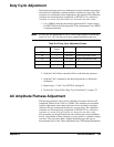
1. Use a DMM to measure the function generator DCV output voltage
for SETUP 60 in the following table. These adjustments use a HIGH
Z output termination.
Note For this test, the DMM must be set to a fixed range capable of measuring
from +10 V to -10 V. Do not use an auto-ranging function for this test.
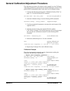
2. Send the CAL:VALue <measured Vdc> to the function generator.
3. Send the CAL? command to the function generator to initiate the
calibration.
4. Repeat steps 1, 2 and 3 for SETUP 61 through 63.
5. Perform the “Square Wave Duty Cycle Verification” on page 172.
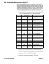
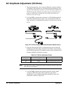
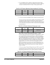
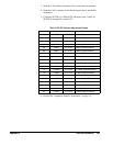
AC Amplitude Flatness Adjustment
The function generator stores eleven calibration constants related to AC
Amplitude Flatness from 1 kHz to 15 MHz. The constants are calculated
from the adjustment value entered and one of two calculation constants
related to the type of measurement device you are using. The calibration
constants are stored following completion of SETUP 82. No calibration
constants are stored if the procedures are aborted at any other setup.
This procedure can be performed with one of three types of measurement
device; a broadband ACrms voltmeter, a power meter, or a thermal voltage
converter. The procedure differs slightly depending upon the type of
measurement device used. These adjustments use a 50 Ω output termination.
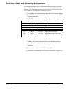
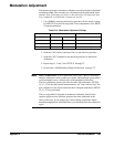
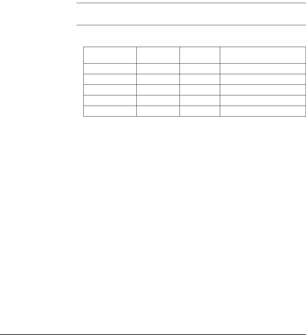
Table D-18. Duty Cycle Adjustment Setups
Nominal
Output
+
SETUP FREQUENCY AMPLITUDE
60 — 10.0 VDC Positive squarewave offset.
61 — -10.0 VDC Negative squarewave offset.
62 300 Hz 0.0 VDC 50% duty cycle squarewave.
63 300 Hz 5.0 VDC 75% duty cycle squarewave