


158 Agilent E1441A Function Generator Tutorial
Appendix C
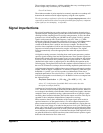
Average Value The average value of an ac waveform is the average of the
instantaneous values measured over one complete cycle. For sine waves, the average
amplitude is zero since the waveform has equal positive and negative half cycles.
Since the quantity of interest is the heating value of the signal, the average value of
a sine wave is taken to mean the average of the full-wave rectified waveform. The
RMS value of a sine wave is equal to 1.11 times the sine wave average amplitude.
This relationship does not hold true for other waveshapes.
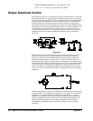
dBm The decibel (dB) is commonly used to describe
RMS voltage or power ratios
between two signals. By itself, a decibel value has no particular meaning. Decibels
are a ratio or comparison unit and have no absolute meaning without knowledge of
a reference or comparison unit. When power comparisons are made to a 1 mW
reference level, the letter m is added to give “dBm”. For power ratios such as dBm,
it is common to specify the resistance loading the voltage source. Often the system
resistance is added to the units by indicating “dBm (50
Ω)” for a 50Ω resistance
system.
dB = 10 x log
10
( P / Pref )
dBm = 10 x log
10
( P / 0.001 )
where power P = V
2
/R
For a 50
Ω resistance, 1 mW of power corresponds to 0.224 VRMS.
Use the following conversions to determine dBm levels when connecting 75
Ω or
600
Ω load resistances.
dBm (75
Ω) = dBm (50 Ω) – 1.75
dBm (600
Ω) = dBm (50 Ω) – 10.79
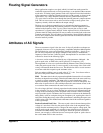
Modulation
Modulation is the process of combining a high-frequency carrier signal and a
low-frequency information signal. How these signals are combined is determined
by the specific type of modulation used. The two most common types of modulation
are amplitude modulation (AM) and frequency modulation (FM). The information
signal that modulates (or varies) the carrier waveform can be of any form — sine
wave, square wave, arbitrary wave, or random noise. In general, the carrier signal
may also be of any shape, but it is usually a sine wave of constant amplitude and
frequency for most communications systems. During modulation, the simple carrier
waveform is converted into a complex waveform by the lower-frequency
information signal. Generally, the higher-frequency carrier waveform is used to
efficiently transmit the complex modulated signal over long distances.
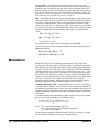
Amplitude Modulation (AM) Amplitude Modulation is a process of producing
a waveform whose amplitude varies as a function of the instantaneous amplitude of
the modulating information signal. In other words, the information signal creates an
amplitude “envelope” around the carrier signal. The Agilent E1441A implements
“double sideband transmitted carrier” amplitude modulation similar to a typical
AM
radio station.
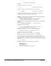
A constant is added to the
AM modulating signal so that the sum is always greater
than zero (for <100% modulation) as this equation shows:
where: "D" is the modulation depth (0 ≤ D ≤ 1.2).
"A
m
" is the modulating signal with peak amplitude ≤ 1.
"F
c
" is the carrier frequency.
An AM waveform with 80% modulation depth. The carrier waveform is a 5 kHz
sine wave and the modulating waveform is a 200 Hz sine wave.
1 D+ A
m
×
t
〈〉)
2
π
F
c
×
T
×(
sin
×
2
----
----------------------------------------------------------------------------------
-------