


Agilent E1441A Function Generator Tutorial 161
Appendix C
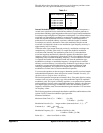
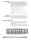
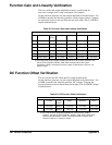
The table below shows the function generator's carrier frequency and burst count
limitations (for sine, square and arbitrary waveforms only).
Internal Modulation Source Internally, the function generator incorporates a
second, lower speed and lower resolution
DDS arbitrary waveform generator to
produce the modulating signal independent of the carrier signal. Internal modulation
waveshapes range in length from 2,048 points to 4,096 points. User-defined arbitrary
waveforms are automatically expanded or compressed in length as needed to fit
within the required modulation waveform constraints. Linear interpolation is
performed on user-defined arbitrary waveforms while the lengths of standard
waveshapes are varied by decimation. Due to the modulation sample rate and
waveform size limitations, the best case modulation signal frequency accuracy is
approximately 0.05% of setting.
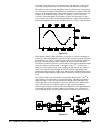
Unlike the main signal output discussed previously, modulation waveshapes are
sampled using a variable “point clock” to sample data loaded in modulation
waveform
RAM. Internally, the modulation point clock (C) and modulation
waveform length are automatically adjusted to produce the modulation signal
frequency desired. For frequencies greater than C/2048, all modulation shapes are
sampled up to the maximum modulating frequency. A new modulation waveform
is computed and loaded into modulation
RAM each time the modulation type,
modulation waveshape, or modulation frequency is changed. Data in standard
arbitrary waveform memory is not affected by modulation signal changes (data is
expanded or compressed and loaded directly into separate modulation
RAM
following computation). No expansion or compression is performed on the
modulation waveform data for certain modulation frequencies.
You can use the equations on the next page to determine specific waveform lengths
and modulation frequencies when more precise control is needed. Normally, you
should not have to perform these calculations.
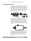
The function generator incorporates an internal 8-bit (
±7 bits peak) digital-to-analog
converter (
DAC) to create an analog copy of the modulation signal for amplitude
modulation (
AM). This signal is internally applied to a conventional four-quadrant
analog multiplier circuit to achieve amplitude modulation. Similarly, the generator
uses digital signal processing to combine the carrier and modulation signals for
frequency modulation (
FM). The FM modulation signal maintains 12-bit resolution
for frequency values.
The following equations and example describe the capabilities and limitations of the
Agilent E1441A's internal modulation signal generator.
Parameter Definitions:
Maximum Point Clock (C) = 5 MSa/ s (for AM)
1.25 MSa/ s (for FM)
Modulation Prescaler (S) = integer numbers (truncated) from 1, 2, 3, ... 2
20
Constant (k) = 4,900 (for AM)
624 (for FM)
Modulation Frequency (F) = 10 mHz to 20 kHz (for AM)
10 mHz to 10 kHz (for FM)
Points (P) = values from 2,048 to 4,096,
Table C-1.
Carrier Frequency Minimum
Burst Count
10 mHz to 1 MHz
>1 MHz to 2 MHz
>2 MHz to 3 MHz
>3 MHz to 4 MHz
>4 MHz to 5 MHz
1
2
3
4
5