


Service Procedures 179
Appendix D
Function Gain and Linearity Adjustment
The function generator stores six calibration constants related to function
gain and linearity. The constants are calculated from the adjustment value
entered. If the calibration procedure is aborted before all setup steps have
been completed, no calibration constants are stored.
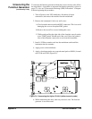
1. Use a DMM to measure the function generator ACrms output voltage
for SETUP 02 in the following table. These adjustments use a HIGH
Z output termination.
2. Send the CAL:VALue <measured Vac> to the function generator.
3. Send the CAL? command to the function generator to initiate the
calibration.
4. Repeat steps 1, 2 and 3 for SETUP 03 through 07.
5. Perform the “Function Gain and Linearity Verification” on page 168.
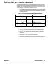
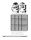
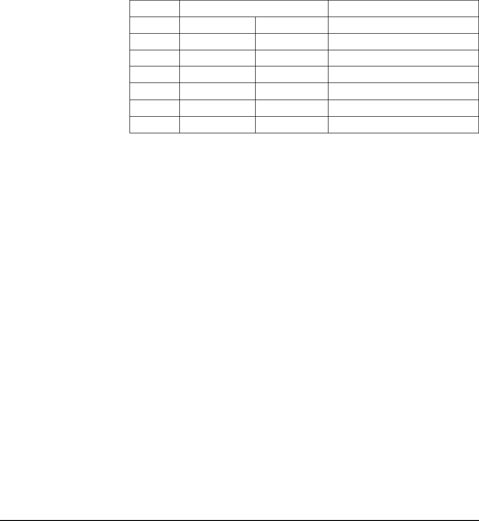
Table D-12. Function Gain and Linearity Adjustment Setups
Nominal Output
SETUP FREQUENCY AMPLITUDE
02 1 kHz 7.07 V rms Adjustment for sine wave gain.
03 1 kHz 5.6 V rms Adjustment for amplitude linearity.
04 100 Hz 5.6 V rms Adjustment for triangle wave gain.
05 100 Hz 5.6 V rms Adjustment for ramp gain.
06 100 Hz 10.0 V rms Adjustment for square wave gain.
07 100 Hz 1.1 Vrms Adjustment for square wave linearity.