


Agilent E1441A Application Information 29
Chapter 2
You cannot use the noise function or dc volts as the AM carrier waveform.
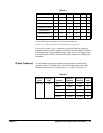
Use the following command to select the shape of the output function:
FUNCtion:SHAPe SINusoid|SQUare|TRIangle|RAMP|USER|DC
You can also use the APPLy command to select the function, frequency,
amplitude, and offset with a single command. Because the APPLy command
also changes duty cycle, modulation type, trigger source, and trigger slope,
you must place the APPLy command first in any sequence of configuration
commands.
AM Carrier Frequency Carrier frequency: 100 µHz to 15 MHz (100 kHz for triangle and ramp).
The default is 1 kHz.
For arbitrary waveforms, the maximum carrier frequency depends on the
number of points specified in the waveform. The five built-in arbitrary
waveforms can be output at a maximum of 5 MHz.
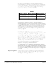
Use the following command to set the carrier frequency:
FREQuency <frequency>|MINimum|MAXimum
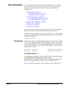
Amplitude Modulating
Waveform Shape
The function generator will accept an internal modulating signal, an external
modulating signal, or both.
Modulating waveform shape (internal source): Sine, Square, Triangle,
Ramp, Noise, or Arbitrary waveform. The default is Sine.
You can use the noise function as the modulating waveform. However, you
cannot use the noise function or dc volts as the carrier waveform.
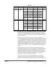
Use the following command to set the modulating waveform shape:
AM:INTernal:FUNCtion SIN|SQU|TRI|RAMP|NOIS|USER
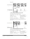
Amplitude Modulating
Waveform Frequency
The function generator will accept an internal modulating signal, an external
modulating signal, or both.
Modulating frequency (internal source): 10 mHz to 20 kHz. The default is
100 Hz.
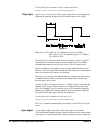
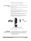
The sync signal for
AM is referenced to the modulating signal (not the
carrier). A momentary
TTL “high” pulse (> 200 ns) is output at each
zero-crossing point of the modulating signal. The signal is output from the
front-panel SYNC terminal.
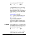
Use the following command to set the modulating waveform frequency:
AM:INTernal:FREQuency <frequency>|MINimum|MAXimum
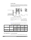
Amplitude Modulation
Depth
The modulation depth is expressed as a percentage and represents the extent
of the amplitude variation. At 0% modulation, the output amplitude is half
of the selected value. At 100% modulation, the output amplitude equals the
selected value.