


Service Procedures 173
Appendix D
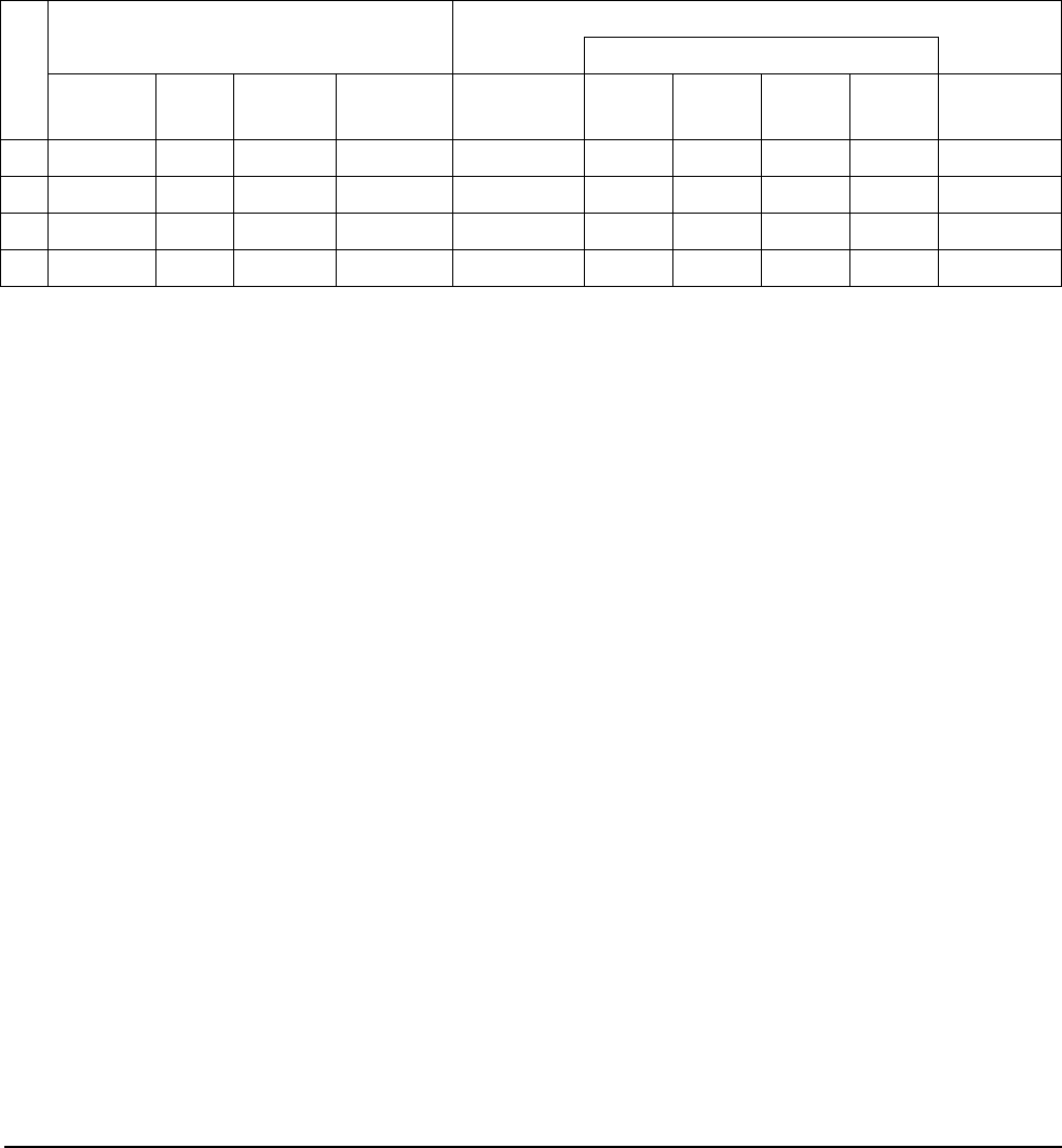
Distortion
Verification
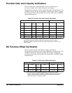
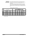
This test checks the Harmonic Distortion at selected frequencies and
harmonics. This test requires the use of a spectrum analyzer with dynamic
range, frequency range, and resolution bandwidth adequate for the
measurement.
Select each function generator output in the table below. Use a spectrum
analyzer connected to the function generator output. Set the fundamental
frequency reference to 0 dB and measure the 2nd through 5th harmonic
frequencies relative to this reference. This test is a 50 Ω output termination
test.
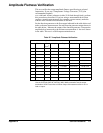
Table D-10. Distortion Verification
Agilent E1441A
Measurement
harmonic
Function Out
Te r m
a
Ampl Freq Fundamental 2nd 3rd 4th 5th Amt below
reference
O Sine wave 50 Ω 1.1 Vrms 20.00 kHz reference 40 kHz 60 kHz 80 kHz 100 kHz > 70 dB
O Sine wave 50 Ω 1.1 Vrms 100.00 kHz reference 200 kHz 300 kHz 400 kHz 500 kHz > 60 dB
O Sine wave 50 Ω 1.1 Vrms 1.00 MHz reference 2 MHz 3 MHz 4 MHz 5 MHz > 45 dB
O Sine wave 50 Ω 1.1 Vrms 15.00 MHz reference 30 MHz 45 MHz 60 MHz 75 MHz > 35 dB
a.The E1441A has a fixed output impedance of 50 Ω on the "Output" terminal. Use the OUTPut:LOAD 50 | INFinity
| MIN | MAX command to set the output termination. HIGH Z assumes no load on output. 50 Ω assumes a 50 Ω
± 0.1 Ω load on output.