


16 Agilent E1441A Function/Arbitrary Waveform Generator Module Setup
Chapter 1
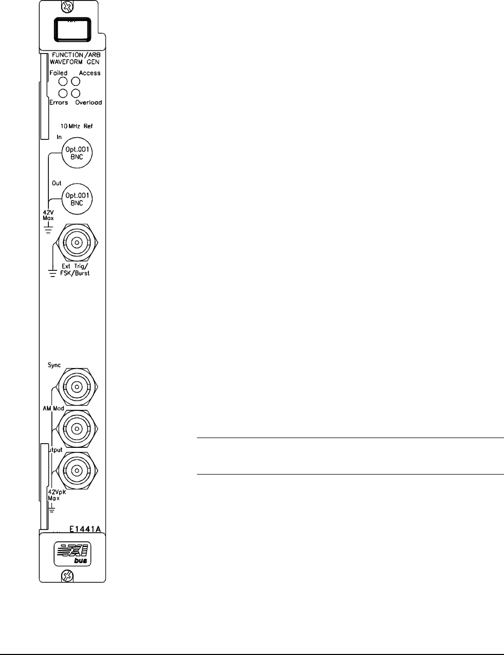
Faceplate Indicators and Connectors
Faceplate Indicators
"Failed" turns on momentarily during the function generator's power-on
self-test. If the function generator successfully establishes internal
communication, the indicator turns off. If the function generator fails to
establish internal communication, the indicator remains on.
"Access" turns on only when the resource manager is communicating with the
function generator.
"Errors" turns on only when an error is present in the function generator's
error queue. The error can result from improperly executing a command or the
function generator being unable to pass a part of self-test or calibration. Use
the SYST:ERR? command repeatedly to clear the error queue. A response of
+0,"No error" indicates the error queue is empty. See Appendix B, Agilent
E1441A Function Generator Error Messages, for a list of all errors.
"Overload" turns on when the function generator senses a signal applied to the
output terminal that exceeds the present output level. The output terminal is
disconnected while the "Overload" light is on.
Option 001 Phase-Lock 10 MHz Reference Terminals
These connectors allow synchronization between multiple Agilent E1441As
or to an external 10 MHz clock signal. Additionally, option 001 allows phase
offset control.
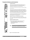
Standard Input/Output Terminals
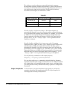
The function generator's faceplate contains the following terminals:
1. External Trigger/FSK/Burst modulation input terminal
2. Sync signal output terminal for all standard output functions
3. AM Modulation input terminal
4. Output terminal
Note The outer shell of the "Ext Trig/FSK/Burst" BNC connector is
connected to chassis. All other BNC connectors are floating.
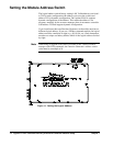
Figure 1-2. Function Generator Terminals