11-14 • E2 RX/BX/CX I&O Manual 026-1610 Rev 13 14-SEP-2011
Full OFF setpoint). Based on this comparison, the anti-
sweat heaters will do one of three things:
• If the input is equal to or above the Full ON set-
point, the heaters remain ON 100% of the time.
• If the input value is equal to or below the Full OFF
setpoint, the heaters will be ON 0% of the time
(fully OFF).
• If the input value is between the Full ON and Full
OFF setpoint, the heaters will be pulsed ON for a
percentage of the specified time interval. The per-
centage is determined by proportionately measuring
where the dewpoint falls between the range of val-
ues formed by the two setpoints.
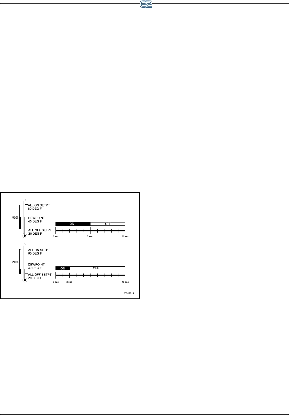
Figure 11-6 shows an example of how anti-sweat con-
trol works. The setpoints (Full ON dewpoint= 80°F, Full
OFF dewpoint = 20°F) form the range of dewpoints across
which the heaters will be pulsed. When the measured dew-
point is 45°F (directly in between both setpoints), the per-
centage will be 50%, and the heaters will be pulsed ON for
5 seconds of the defined 10-second interval. If the dew-
point drops to 30°F, the percentage will lower to 20%, and
the heaters will be on only 2 seconds out of every 10.
11.4.5.1 Dewpoint Input Sources
Dewpoint control inputs for the case controller’s Anti-
Sweat algorithms must come from a dewpoint probe set up
on the E2 I/O Network.
Note that when using a dewpoint probe on the E2 I/O
Network, the case controller will rely on the E2 to provide
the anti-sweat control value. If communications with the
E2 are lost, the case controller will enter Fail-Safe Mode
(see Section 11.4.11) and default to a fixed 50% output.
11.4.6 Dual Temp Control
A case controller can be configured to change its case
temperature, alarm, and superheat setpoints when an exter-
nal digital input is switched ON or OFF.
The user simply connects the digital switch to an input
point on the RS485 I/O Network and configures the case
controller to read that input as a dual temp switch. When
the dual temp switch is ON, the case controller overrides
its normal case temperature, alarm, and superheat set-
points with a set of user-specified alternate setpoints.
11.4.7 Fan Control
A relay on the power module activates the case fans.
The fans will be ON while in refrigeration mode, and they
may be programmed to be either ON or OFF when the
temperature setpoint is satisfied and refrigerant is not
flowing.
When in defrost mode, the fans default to OFF, but
they may be programmed by the user to be either ON or
OFF.
When a liquid-side CCB is in Recovery Mode (see
Recovery Mode, page 9-10), Fan Control may be config-
ured to delay the activation of fans for a user-specified
amount of time. This delay helps keep the fans from
splashing excess moisture that may still be on the coil.
11.4.8 Light Control
Lights are activated and deactivated by a relay on the
power module.
The case controller itself does not have any special
control algorithm for the case lights other than to leave the
lights ON during normal operation. There are only two
cases where the lights are not always ON:
1. An override from an E2 takes over control of the
case lights. This override may take the form of a
manual switch or a schedule output.
2. If the case controller is set up to use Walk-In Box
Control, the case lights default to OFF and only
come ON when the door switch is tripped. See
Section 11.4.10, Walk-In Freezer Control.
11.4.9 Clean/Wash Mode
Clean Mode is a special kind of case deactivation
designed specifically for washing or performing mainte-
nance on the case.
Clean Mode is initiated by activation of a cleaning
switch input or by a command sent from a Hand-held Ter-
minal or an E2. During Clean Mode, refrigerant flow is
turned OFF, all fans and anti-sweat heaters are deacti-
vated, and the lights are turned either ON or OFF as pro-
grammed by the user.
Figure 11-6
- Illustration of Anti-Sweat Control


