


6-18 • E2 RX/BX/CX I&O Manual 026-1610 Rev 13 14-SEP-2011
32
2
5
3
4
1
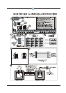
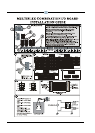
1. Connect 16A1 to the RS485 I/O Network.
2. Set the network address on the first five
rockers of dip switch S3.
3. Set the network baud rate using rockers 6
and 7 of dip switch S3.
4. Set RS485 termination jumpers UP (term) if
at either end of a daisy chain. Otherwise, set
jumpers DOWN (not term).
Note: If you change any dip switch settings
while the board is powered, disconnect the
power and re-power the board to reset.
5. Connect board to the 24VAC
secondary of the power transformer.
center-tapped
T
O
O
T
H
E
R
R
S
4
8
5
D
E
V
I
C
E
S
T
O
O
T
H
E
R
R
S
4
8
5
D
E
V
I
C
E
S
2345678
1
ON
2345678
1
ON
2
3
4
5
6
7
8
1
ON
2345678
1
ON
2345678
1
ON
2345678
1
ON
2
3
4
5
6
7
8
1
ON
2345678
1
ON
2345678
1
ON
2345678
1
ON
2
3
4
5
6
7
8
1
ON
2345678
1
ON
2345678
1
ON
2345678
1
ON
2
3
4
5
6
7
8
1
ON
2
2
3
3
4
4
5
5
6
6
7
7
8
8
1
1
ON
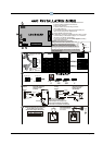
BOARD 1 BOARD 2 BOARD 3
BOARD 4
BOARD 5 BOARD 6 BOARD 7
BOARD 8
BOARD 9 BOARD 10
BOARD 11
BOARD 12
BOARD 13 BOARD 14
BOARD 15
BOARD 16
ADDRESS
2
2
2
3
3
3
4
4
4
5
5
5
6
6
6
7
7
7
8
8
8
1
1
1
BAUD RATE
9600 baud
19200 baud
16AI INSTALLATION GUIDE
DAISY CHAIN CONFIGURATION
SET TERMINATING JUMPERS:
UP DOWN DOWN UP
JU1 JU2 JU3 JU1 JU2 JU3
UP
DOWN
1
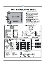
WIRING FOR 640-0056, 56VA Transformer,
and 640-0080, 80VA Transformer
PRIMARY SIDE
240 208
C
120
(
N
E
U
T
R
A
L
)
(
H
O
T
)
120/208/240 VAC
SECONDARY SIDE
24V CT 24V
AC1
0V
AC2
AC1
AC2
24VAC Center-Tapped Transformer
24VAC Center-Tapped
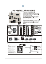
L2
L1
Three-conductor non-shielded cables
are the recommended wire
for connecting between the
center-tapped transformer
and I/O boards.
Power Wiring Types:
14 AWG Belden 9495
18 AWG Belden 9493
Earth ground the
0V (center-tapped)
terminal of each board
0V
2
3
4
5
SHIELDED TWISTED PAIR
BELDEN #8761. FOR PLENUM,
USE BELDEN #82761 OR #88761
OR EQUIV.
WIRE + to + (same color)
WIRE 0V to 0V
WIRE - to - (same color)
(Terminated)
(Not Terminated)
(Term)
(Term)