Boiler Software Overview • 11-55
11.23.4.1 Digital Scroll Compressor
MCC can also utilize a single Digital Scroll Compres-
sor. The assumption is that one of the Compressor Control
Modules in the system may have a digital scroll instead of
a standard scroll compressor installed. The Digital Scroll
Compressor may not be the same size as the fixed scroll
compressors. When a Digital Scroll Compressor is defined
in the application, MCC will utilize the compressor con-
trol modules with the digital scroll at all times, modulating
the capacity of the compressor to maintain the Chilled
Supply Temperature setpoint. All other compressor con-
trol modules will be turned ON or OFF based on the rota-
tion sequence defined above. Based on this strategy, the
digital scroll compressor will have the fewest cycle counts
and the most runtime of all the compressors in the system.
11.23.4.2 Variable Frequency Drive Com-
pressor
MCC can utilize one compressor with a variable fre-
quency drive. The method of control will be similar to the
digital compressor strategy. The application will continue
to allow only one variable capacity device to be defined in
the system, making the Variable Frequency Drive and Dig-
ital compressor options mutually exclusive.
If a Variable Frequency Drive compressor is to be used
and it is a Control Techniques drive using the Modbus
communication interface, the Control Techniques Drive
association menu will support associating the drive to an
MCC.
11.23.4.3 Unequal Capacity Compressors
Optionally, the MCC can support different capacity
compressors. When this option is selected, the capacity of
each defined compressor will be user specified. The con-
troller will evaluate the capacities of all the compressors to
determine the appropriate compressor to switch on or off
in order to maintain the Supply Temperature at setpoint.
When unequal capacity compressors are defined, the
controller will not use a simple round robin approach to
switching compressors on or off (as with equal capacity
compressors) and therefore compressor runtimes may vary
significantly over time. However, for those compressors
defined with identical capacity, the algorithm will attempt
to keep both runtimes and cycle counts as even as possi-
ble.
11.23.5 Bypass Valve Control
MCC can utilize the Chilled and Condenser Bypass
Valves. These valves will be modulated to maintain user
defined differential setpoints. For each valve, as the differ-
ential pressure rises above the setpoint, the valve will
modulate open. When the differential pressure falls below
setpoint, the valve will modulate closed.
11.24 Boiler
The BX-300 and BX-400 will default to a maximum of
two Boiler applications. Other models will have to license
the Boiler Application. The Boiler will be available only
for E2 versions 3.0 and higher.
11.24.1 Overview
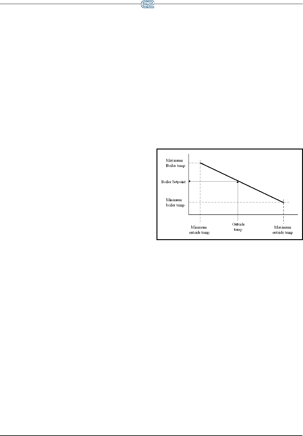
The Boiler can be controlled two ways, via the boiler
temperature or the boiler pressure. The E2 uses the current
outside air temperature to calculate a new boiler control
setpoint. If the boiler temperature (or boiler pressure) is
less than the setpoint value then the boiler is turned ON.
Otherwise it is turned OFF. The algorithm will work in an
inverted fashion if the Minimum Outside Air Temperature
is greater than the Maximum Outside Air Temperature.
An Outside Air Temperature Boiler On and an Outside
Air Temperature Boiler Off can be defined. If the outside
air temperature is lower than the Outside Air Temperature
Boiler On the boiler is turned ON. If the outside air tem-
perature is higher than the Outside Air Temperature Boiler
Off the boiler is turned OFF.
If defined, the Outside Air Temperature Boiler Off
must be greater than the Outside Air Temperature Boiler
On.
11.24.2 Alarms
There are four advisory generated by the Boiler Appli-
cation:
• High Temperature
• Low Temperature
• High Pressure
• Low Pressure
Each advisory will have an associated type, priority,
and delay.
Figure 11-1
- Temperature Ranges


