Wire Restrictions Echelon Network and Hardware Setup • 8-3
8.4.1 Using a Termination Block
(P/N 535-2715) to Terminate a Daisy
Chain
Some Echelon Network devices, notably TD3s, have
no on-board means of terminating. For some other
devices, it is inconvenient to use the jumpers supplied for
termination (the CC-100/CS-100 case controllers, for
example, require the enclosure to be removed to set the
jumper).
To remedy these problems, Retail Solutions supplies
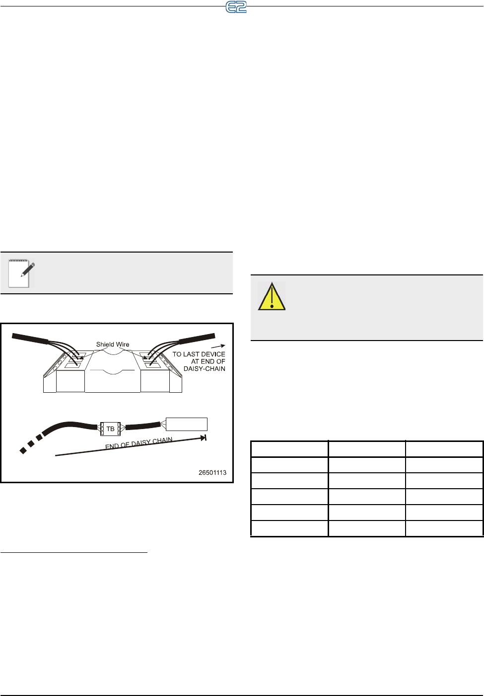
termination blocks that can be wired to the end of an Eche-
lon cable segment. This termination block uses the same
three-pin connector as all other Echelon devices. Wire the
two signal wires to the outside terminals, and connect the
shield to the middle terminal (see Figure 8-4).
8.5 Wire Restrictions
Maximum Total Segment Length
The total amount of wire used to connect all E2s and
associated controllers in a single segment (not including
devices on the other side of routers) cannot be longer than
4592 feet (1400 meters). If the total length of cable used is
longer than 4592 feet, a repeater or router will be required.
Routers act as communication gateways that reduce
the amount of network traffic. They are used when net-
works exceed their 63-node limit. Adding a router allows
you to add another daisy-chain segment of 4592 feet with
a maximum of 63 more nodes.
Repeaters boost signal strength and are only used in
instances where a segment of 63 nodes or less uses more
than 4592 feet of Echelon cable.
Refer to the Router and Repeater Installation Guide
(P/N 026-1605), for information about router and repeater
placement.
8.6 Installing Echelon
Devices
The E2 control system has several types of peripheral
control boards that communicate using the Echelon Net-
work: the 16AIe analog input board, the 8ROe relay out-
put board, the CC-100/CS-100 series of case control and
case circuit control boards, and the ESR8 board.
8.6.1 Powering Echelon Devices
All Echelon devices require 24VAC Class 2 power.
Retail Solutions specs several sizes of transformers to
accommodate the full range of Retail Solutions’ Echelon-
compatible products. Table 8-3 lists each transformer’s
part number and rating.
To select a power transformer for one or more Echelon
devices:
1. Determine what the total VA is for the boards
and controllers that will be powered by the
transformer (see Table 8-4).
Example: Two TD3 boards (4 VA each), and
one E2 (40 VA) board are to be powered by
one transformer. The total VA is:
NOTE: The recommended termination proce-
dure for all Echelon devices is the termination
block.
Figure 8-4
- Placement and Wiring of the Termination Block
CAUTION: Do not power Echelon devices
with the same 56VA and 80VA transformers
used to power the I/O Network. Echelon
devices require Class 2 power to operate, which is not
supplied by the I/O board transformers.
Xformer P/N VA Rating Input Voltage
640-0039 10 VA 110 VAC
640-0041 50 VA 110 VAC
640-0042 50 VA 220 VAC
640-0050 75 VA 110 VAC
640-0045 75 VA 220 VAC
Table 8-3
- Class 2 Transformers for Echelon Devices


