3-10 • E2 RX/BX/CX I&O Manual 026-1610 Rev 13 14-SEP-2011
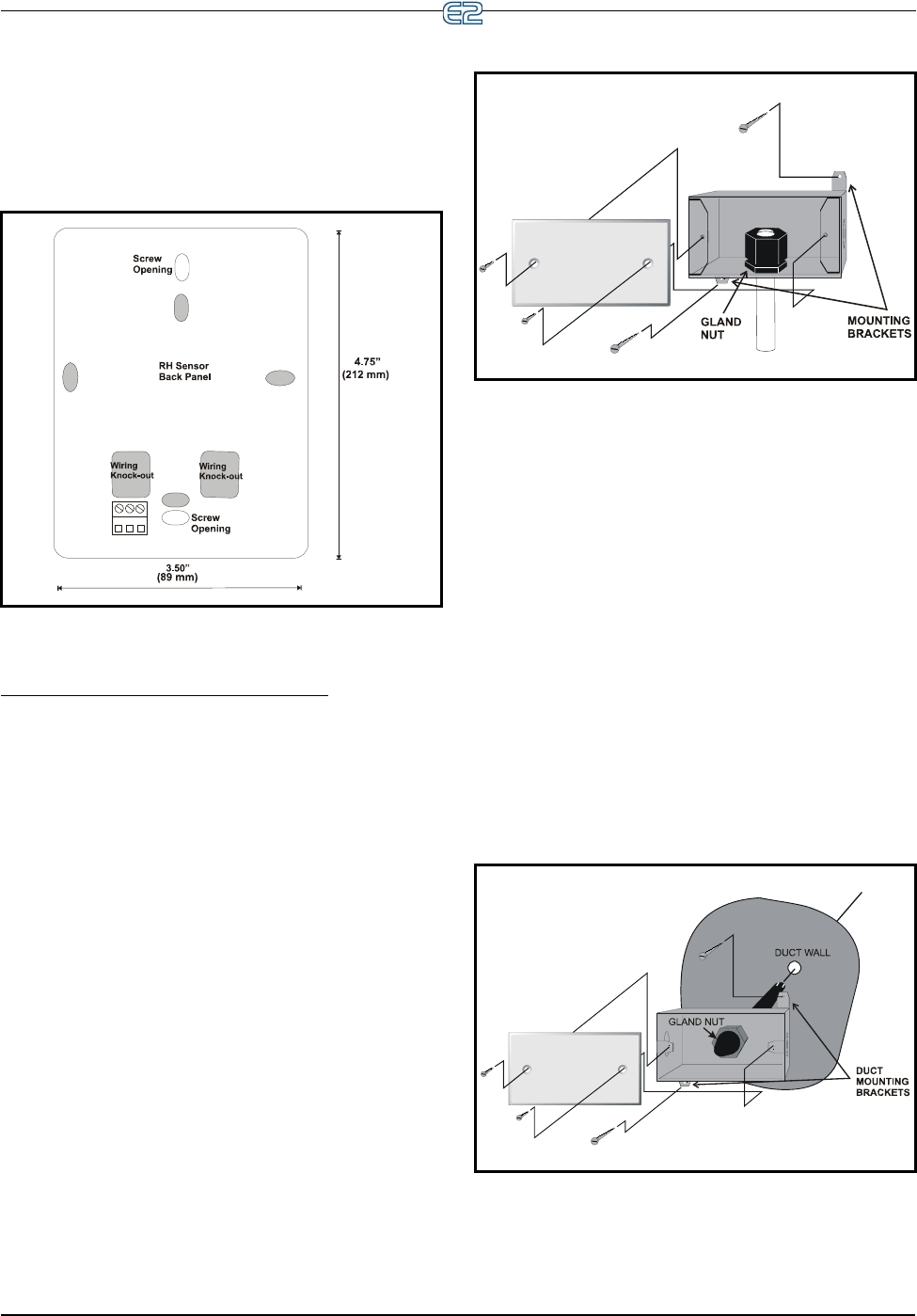
4. Mount the back plate to the wall using the
two open mounting holes on the top and bot-
tom of the plate.
5. Replace the cover on top of the back plate by
lining up the tabs, and snap the lid back into
place.
3.5.8.2 Outdoor RH Sensors
The outdoor RH sensor (P/N 203-5761)
The outdoor RH sensor (P/N 203-5761) should always
be mounted on the north side of the building if in the
Northern Hemisphere, or on the south side if in the South-
ern Hemisphere. The sensor should be mounted under an
overhang or otherwise out of direct sunlight (if possible).
Mount the RH sensor (P/N 203-5761) as follows:
1. Secure the rear side of the enclosure to the out-
side wall using the two mounting brackets, as
shown in Figure 3-26. The tube holding the sen-
sor element should point straight down.
2. If you will be running the sensor cable through
the wall behind the sensor, cut or drill a hole in
the wall through the hole in the enclosure.
3.5.8.3 Duct-mounted Insertion RH
Probe
Retail Solutions specs a duct-mounted relative humid-
ity (RH) sensor (P/N 203-5771) with a 0-5VDC output for
use in building control and anti-sweat control applications
using Retail Solutions input boards.
1. Cut a small circular hole in the duct large enough
for the sensor tube to fit through.
2. Bolt the sensor enclosure against the outside of
the duct wall so that the sensor element fits
through the hole and into the duct. The enclosure
may be mounted horizontally, as shown in Fig-
ure 3-27 or vertically. The screws should be tight
enough for the foam gasket around the bottom of
the sensor to form an airtight seal between the
hole in the duct wall and the outside air.
Figure 3-25
- Indoor RH Mounting Dimensions
Figure 3-26 - Outdoor RH Sensor - Exploded View
Figure 3-27 - Duct-mounted RH Sensor - Exploded View


