


6-20 • E2 RX/BX/CX I&O Manual 026-1610 Rev 13 14-SEP-2011
LAST XEV22D
DEVICE
13
14
15
17
12
4
5
+
_
16
XEV22D
13
14
15
17
12
4
5
+
_
16
MODBUS TERMINATION
BLOCK 150 OHM
TERMINATE LAST DEVICE ONLY
(P/N 535-2711)
MODBUS SHIELD TO
TERMINAL OF DEVICE
PIN 16
FROM E2 PIB BOARD OR
OTHER RS-485 MODBUS
DEVICE
WIRE BLACK TO +
WIRE WHITE TO
_
REVERSE POLARITY OF
+/- ON RS-485 CABLE
FROM E2 TO DEVICE
WIRE BLACK TO +
WIRE WHITE TO
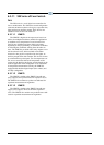
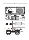
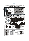
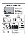
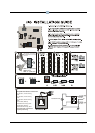
1. Connect the MODBUS Network to the RS-485 Connector
on the E2 PIB board (Belden 8641 recommended).
2.
3. Position the three termination jumpers to the UP
(terminated) position to provide RS-485 termination at the E2.
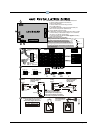
4. Do not connect the shield of the MODBUS network to the
E2 PIB center terminal. Instead, use a 100 ohm ½ watt resistor
to connect the MODBUS cable shield to earth ground.
5. At the XEV22 device, wire the MODBUS cable to the RS-485 +/-
terminals and connect the MODBUS shield to the pin 16
terminal.
6. Terminate the end of the MODBUS network at the last device
on the daisy chain with the MODBUS termination block
(P/N 535-2711), or by connecting a 150 ohm resistor between
the MODBUS +/- terminals.
For more information, please refer to the XVE22D user manual
.
Note to wire the RS-485 +/- polarity at the E2 in the
reverse of the XEV22D device.
P/N 026-1206
XEV22D DRIVER TO E2
INSTALLATION GUIDE
0V
+
RS-485 -2A
0V
+
RS-485
637-4890 COM4 ON E2 PIB
HOT KEY
13
14
15
16
17 18 19 20 21
12
4
5
6
7
8
XEV22D
11 12
0V
+
RS-485 -2A
0V
+
RS-485
637-4890 COM4 ON E2 PIB
100 OHM
½ WATT
TO DEVICE
EARTH GROUND
CONNECTION
RESISTOR